By KJW
This paper proposes an exploratory plasma-propulsion architecture in which spacecraft-scale magnetic geometry is used to organize, accelerate, and progressively release a mixed-species plasma before the plasma reaches a fully closed, independently persistent plasmoid state. The proposed working medium is a predominantly hydrogen plasma containing approximately 3% argon. Rather than treating the mixture as a homogeneous propellant, the concept attempts to exploit differences among electron, hydrogen-ion, and argon-ion response rates as the plasma passes through an extended magnetic-lobe corridor generated and modified by external boom-mounted field shapers.
The proposed lobe geometry performs several functions within a single continuous field structure. An upstream plasma source introduces the working species into a narrowing interaction region; the converging lobes establish a controlled corridor in which species-dependent transport, current organization, and sheet formation may develop; an intermediate region permits partial relaxation and reorganization; and a downstream reduction in lobe confinement progressively reduces spacecraft coupling and permits directed exhaust release. The architecture therefore does not require a completely formed field-reversed configuration, flux rope, or autonomous plasmoid to be produced before useful acceleration begins. Instead, it seeks to exploit an intermediate pre-closure state—designated Q3− within the developmental framework used in this study—while the structure remains strongly coupled to spacecraft-generated fields.
A nine-stage mechanical chain is developed linking species differential response, corridor organization, identifiable forming mass, organized current, spacecraft coupling, Maxwell stress, variable-mass acceleration, geometric widening, and release. Additional analysis considers electron-current closure, residence time, temporal and geometric rate mismatch, bounded transitional behavior, energy and momentum conservation, structural and electrical coupling through the boom/shaper system, exhaust divergence, and the potentially distinct spatial supports of the participating mass, organized current, and species-overlap regions.
The proposal arose through a sequence of mathematical, reduced-order, and MHD-consistent exploratory models using the computational tools available to the study. These models repeatedly suggested species-dependent organization, transitional sheet-like structures, bounded pre-closure behavior, finite residence, spatial overlap and breakout regions, and progression toward more autonomous organized states. They do not constitute a full multifluid-MHD solution of the proposed vehicle geometry. Rather, they provide the motivation for asking whether the combined mechanism survives when electron, hydrogen, and argon dynamics, electromagnetic energy transfer, field geometry, and spacecraft reaction forces are treated simultaneously at higher fidelity.
No claim is made here that the complete propulsion system has been experimentally demonstrated, nor that a net efficiency or mission-performance advantage has been established. The constituent proposal is instead constructed from known electromagnetic, plasma, mechanical, and conservation-law mechanisms, combined in a vehicle-scale geometry whose central hypothesis remains testable: can an extended magnetic corridor exploit differential species response to create a sufficiently coherent, sufficiently long-lived, externally coupled pre-closure plasma structure that can receive useful axial Maxwell stress and then release that momentum progressively as the confining geometry naturally recedes?
High-performance plasma propulsion presents an unusual systems problem. Producing high particle velocity is only one requirement. A useful propulsion system must create and organize the plasma, transfer energy into directed momentum, maintain a reaction path to the spacecraft while that momentum is being transferred, control unwanted transverse motion, and finally permit the accelerated plasma to leave without returning a substantial portion of its acquired momentum to the vehicle or surrounding field structure.
A number of established and experimental propulsion approaches address different parts of this problem. Electrostatic and electromagnetic thrusters accelerate charged particles directly. Magnetic nozzles guide expanding magnetized plasma. Magnetoplasmadynamic systems use electromagnetic body forces to accelerate conductive plasma. Field-reversed-configuration and plasmoid propulsion research has investigated the formation and acceleration of compact magnetically organized plasma structures. NASA-supported work has included FRC/plasmoid formation, acceleration and detachment, including concepts in which a formed translating plasmoid receives additional directed kinetic energy through sequential downstream magnetic coils.
These approaches establish an important point for the present proposal: magnetically organized plasma can be formed and accelerated, and its subsequent interaction with externally imposed magnetic fields is a legitimate propulsion research problem. They also expose a systems question that became central to the present study. If a plasma structure is deliberately driven toward a sufficiently complete and independently persistent magnetic configuration, is it always advantageous to complete that formation before extracting the desired spacecraft-coupled acceleration?
The present work explores a different ordering of the problem.
Rather than requiring:
formation→completed plasmoid→acceleration→detachment
the proposed architecture investigates:
species differentiation→spatial organization→partial formation→acceleration while externally coupled→progressive geometric release.
The distinction is important. A completed plasmoid may be a desirable exhaust structure for one propulsion architecture. It need not be the optimum intermediate state for another.
The concept developed here therefore focuses on the period before complete autonomous closure. Within the developmental terminology used throughout this study, an incoming organized state is denoted Q2, while a sufficiently complete higher-order closed structure is denoted Q3. The propulsion region of interest lies between them:
Q2→corridor→sheet→Q3−→Q3.
Here Q3− does not designate a newly established plasma species or experimentally recognized plasma phase. It is an operational label for a partially organized, pre-closure state possessing enough collective structure to identify a participating mass and organized current while still retaining substantial coupling to the spacecraft-generated field. A more formal operational definition is developed later in the paper.
This distinction emerged from the exploratory modeling rather than being imposed as the original desired result. Early investigations followed higher-order closure and rope-like organization because such structures represented a natural endpoint of increasing plasma organization. As those models progressed, however, complete closure became less interesting for the vehicle architecture than the transition leading toward it. The intermediate state retained properties that were potentially valuable for propulsion: differential species behavior, externally controllable geometry, organized current, finite residence, and a forming mass that had not yet become completely independent of the spacecraft field.
The engineering question consequently shifted from:
How can the vehicle produce and propel a completed plasma structure?
to:
Can the vehicle exploit the formation process itself?
That change motivates the architecture developed here.
The proposed vehicle uses a predominantly hydrogen plasma with a small argon fraction, provisionally taken as approximately 3% for the simplified study. The mixture is introduced from a central plasma source into a magnetic environment generated by an extended boom-and-shaper system.
The external field is intentionally not treated merely as a conventional short magnetic nozzle.
Instead, the spacecraft generates extended lobes that define a substantially longer interaction corridor. Within that geometry, the plasma encounters regions of narrowing confinement, differential transport, sheet formation, relaxation, renewed organization, acceleration, and eventual widening.
The architecture deliberately exchanges compactness for interaction distance.
A short propulsion chamber may be required to accomplish several processes over a comparatively limited axial distance:
injection→ionization→organization→acceleration→detachment.
The present proposal asks whether some of those requirements can instead be distributed over an extended vehicle-scale magnetic environment:
formation over distance→organization over distance→acceleration over distance→release over distance.
A corridor measured in hundreds of meters or potentially kilometers is therefore not simply a larger version of a conventional engine chamber. Its length supplies residence time.
For a characteristic organized-region length Lorg and axial transport velocity vz,
τres∼vzLorg.
Increasing the available interaction length can therefore give electron-current organization, differential ion response, field/plasma energy exchange, and axial Maxwell stress more time over which to develop. It does not reduce the energy required to produce a given exhaust state. It changes the spatial and temporal conditions under which that energy and momentum can be transferred.
This is a central design philosophy of the proposal:
bias and exploit the plasma’s accessible evolution rather than require immediate closure.
The vehicle geometry is therefore intended to establish favorable boundaries and gradients rather than prescribe the trajectory of every constituent particle.
The addition of argon is not proposed merely to increase propellant molecular weight. Hydrogen ions, argon ions, and electrons possess substantially different masses and therefore need not respond identically to changing electromagnetic and geometric conditions.
The electron population responds most rapidly. Hydrogen ions respond on a slower characteristic scale, while the substantially heavier argon ions can exhibit still slower redistribution under comparable conditions. The exact ordering depends on magnetization, collisions, density, temperature, field strength, ionization state, and geometry and therefore requires proper multifluid calculation.
The proposal nevertheless asks whether this differential response can be made useful.
Instead of attempting to eliminate relative species behavior as quickly as possible, the lobe corridor is designed to permit controlled spatial and temporal differentiation while maintaining an overall coupled plasma system.
The resulting conceptual structure contains potentially distinct regions:
VM
for mechanically participating forming mass,
VJ
for organized current,
and:
VO
for substantial hydrogen-argon overlap.
Thus:
VM=VJ=VO
is permitted.
The current-bearing electron-dominated envelope need not occupy exactly the same volume as the H/Ar mass that ultimately receives the momentum. Likewise, localized argon-rich regions need not automatically represent propellant loss if they remain coupled to the force-transmitting current structure.
This spatial distinction becomes important later when Maxwell stress, species breakout, and release are considered.
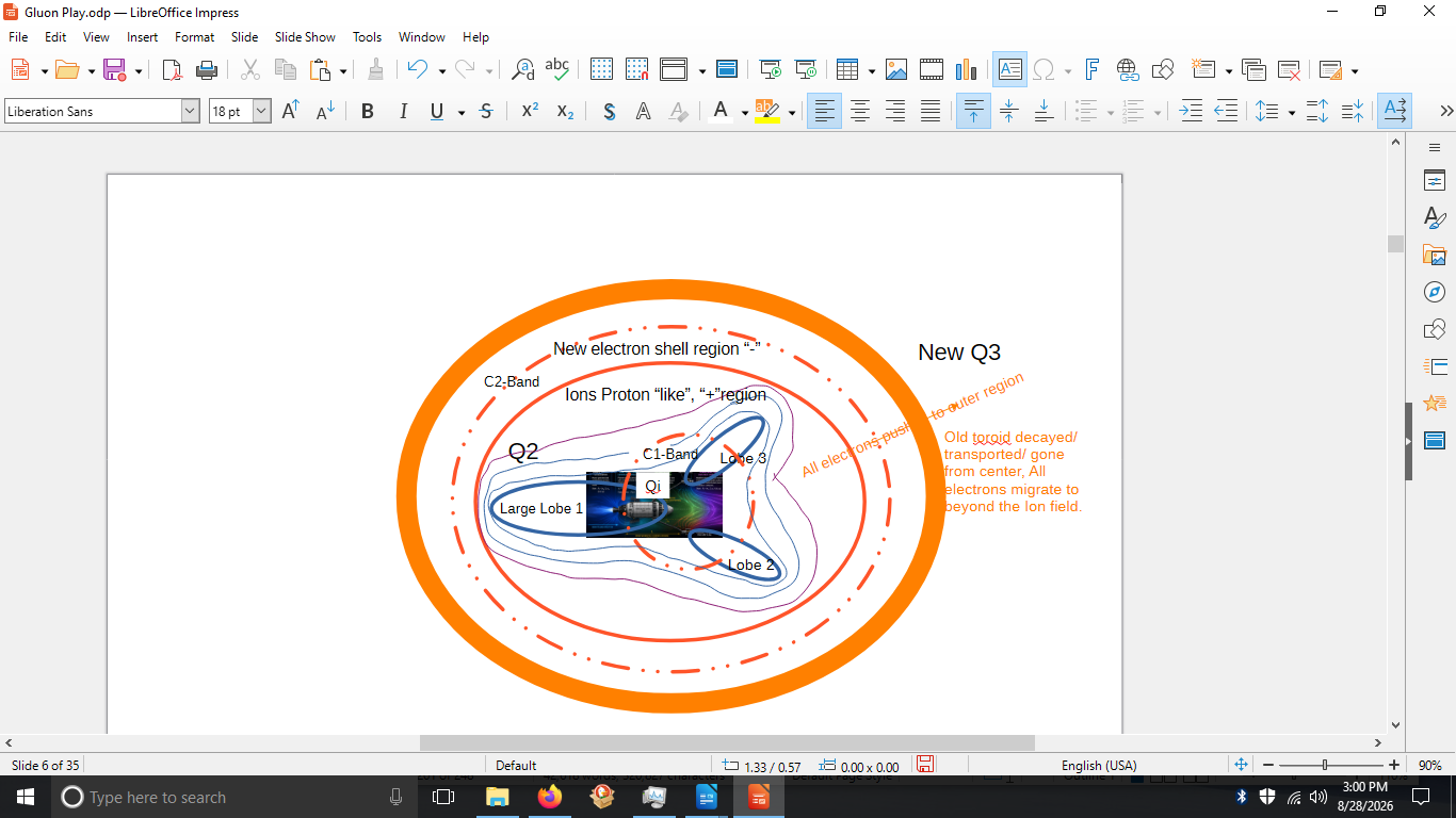
In the developmental framework used during the study, the transition from Q2 toward Q3 exhibited what was termed wobble: an organized state changing sufficiently to explore another configuration while retaining enough persistence to remain identifiable.
For this propulsion proposal, wobble is not an undesirable oscillation added to an otherwise static operating point.
The entire sequence:
Q2→corridor→sheet→Q3−
is the engineered wobble regime.
The desired state is therefore intrinsically nonequilibrium.
Too little organization produces dispersion and weak force transfer. Too much progression toward autonomous closure may reduce the external field authority that the vehicle is attempting to exploit. The useful operating region lies between these outcomes.
The external shapers consequently need not force a prescribed microscopic plasma configuration. Their proposed role is to alter corridor radius, field curvature, gradients, and local confinement sufficiently to keep the evolving structure within a useful range while axial momentum is transferred.
This distinction also motivates the later consideration of mechanically and electrically responsive shapers. If the large-scale lobe is itself a dynamically preferred field configuration, the shapers may eventually prove to function more effectively as boundary conditioners, attractors, or stabilizers than as elements that independently impose every part of the field. Possible field-energy recirculation, electrical regeneration, and coupled structural/electrical resonance are discussed later as exploratory hypotheses; none is required for the core propulsion mechanism proposed here.
The architecture presented in this paper was not developed from a full spacecraft-scale multifluid-MHD simulation. Such a calculation was beyond the computational tools and resources available to this exploratory study.
The development instead proceeded incrementally.
Conventional electromagnetic and plasma relations were retained where applicable. MHD-consistent descriptions and reduced models were used where the available tools permitted them. Mathematical and numerical toy systems were then used to examine questions including species differential response, corridor formation, residence, sheet organization, progressive closure, spatial breakout, external steering, and the transition between externally dependent and more autonomous plasma organization.
Those models produced enough recurring structure to motivate the present vehicle hypothesis. In particular, they suggested that the transition toward a more completely organized state could itself contain exploitable spatial structure and finite residence rather than behaving only as an instantaneous passage between two states.
They do not establish that the proposed H/Ar/electron system will produce the required structure in the actual spacecraft geometry.
The distinction is fundamental:
reduced-model evidence=multifluid-MHD validation=experimental demonstration.
Section 11 therefore returns explicitly to the exploratory models, what they produced, where they failed or required reinterpretation, and which conclusions survived the development process.
The paper similarly distinguishes established physical mechanisms from reduced-model results, model-derived interpretations, engineering hypotheses, and speculative extensions. An Evidence Ledger later summarizes those categories for the complete proposed mechanism.
The objective is not to substitute a developmental framework for plasma physics. It is to use the framework and reduced modeling to formulate a sufficiently specific physical question that a higher-fidelity plasma model can answer.
The resulting proposal can be reduced to one central hypothesis:
An extended spacecraft-generated magnetic-lobe geometrymay exploit differential electron/H/Ar response to createa persistent but incompletely closed plasma structurethat remains sufficiently coupled to the spacecraft fieldto receive useful axial Maxwell stress before beingprogressively released by the naturally receding geometry.
If that hypothesis fails under proper multifluid-MHD treatment, the central propulsion proposal fails.
If it survives, subsequent questions of energy efficiency, structural mass, field-generation power, boom dynamics, thermal management, plume divergence, reliability, and mission performance become worth answering.
That is the level at which this paper is intended: a geometrically and mechanically specified propulsion proposal, motivated by reduced modeling, assembled from known physical mechanisms, and advanced to the point where its principal unresolved proposition can be stated and tested.
The proposed architecture did not begin from the assumption that an entirely new plasma-acceleration mechanism was required. Its development instead followed several established and experimental lines of plasma physics that solve different portions of the propulsion problem: direct electromagnetic acceleration, magnetic-nozzle expansion, formation and acceleration of coherent plasma structures, and large-scale interaction between flowing plasma and extended magnetic fields.
The present proposal asks whether those pieces can be arranged differently.
Rather than concentrating formation, organization, acceleration, and detachment within a compact propulsion device, the vehicle itself becomes part of the field geometry. The resulting magnetic lobes provide an extended interaction region through which a working plasma can progressively reorganize while remaining coupled to the spacecraft.
The distinction is therefore primarily one of architecture, geometry, and sequencing, rather than a claim for a new fundamental force.
Electric propulsion encompasses several mature and experimental approaches for converting electrical energy into directed exhaust momentum. Electrostatic thrusters accelerate ions through electric fields, while electromagnetic devices such as magnetoplasmadynamic thrusters use current interacting with magnetic field to generate a plasma body force of the familiar form
f=J×B.
Magnetic nozzles provide another important precedent. Rather than relying upon a solid nozzle wall to direct a high-temperature plasma, an applied magnetic field guides the expansion of magnetized charged particles and assists conversion of plasma energy into directed exhaust.
These technologies demonstrate the fundamental ingredients required by the present proposal: externally generated electromagnetic fields can interact with plasma currents, electromagnetic stress can produce directed plasma momentum, and magnetic geometry can influence the direction and expansion of an exhaust without requiring material contact with the plasma.
The proposed system retains those conventional foundations.
Its departure occurs in the spatial extent and function assigned to the magnetic field.
Instead of treating the applied field primarily as a compact acceleration or nozzle region, the present architecture extends that field outward from the vehicle and uses its geometry to participate in the development of the plasma state itself.
Field-reversed configurations and related plasmoid concepts provide a particularly relevant comparison because they deliberately create coherent magnetized plasma structures and then accelerate them.
NASA and associated research programs have investigated several versions of this general approach. The Field Reversed Configuration Accelerated Space Thruster (FAST) investigated repetitive formation of FRC plasmoids followed by electromagnetic acceleration. Later Plasma Thruster Experiment (PTX) work at NASA Marshall examined pulsed inductive formation and acceleration of FRC-like plasma structures. These programs provide experimental and computational precedent for treating a magnetically organized plasma object as an exhaust structure rather than requiring acceleration of independent ions alone.
Related concepts have investigated downstream magnetic acceleration in which a translating plasmoid encounters sequentially energized magnetic coils. In these systems, formation and acceleration need not occur at exactly the same location; an already organized plasma structure can receive additional directed kinetic energy as it moves through an externally controlled magnetic system.
This work was important to the development of the present proposal because it establishes that the sequence
plasma formation→magnetic organization→electromagnetic acceleration
is not merely hypothetical.
It also highlights the importance of the final part of the sequence:
release or detachment.
A magnetically coherent structure that remains strongly coupled to its generating or accelerating field cannot simply be assumed to constitute useful exhaust. Formation, acceleration, and detachment therefore constitute a coupled engineering problem.
The present proposal does not argue that a fully formed FRC or plasmoid cannot be accelerated or successfully detached. Experimental research provides ample reason to continue investigating those approaches.
Instead, the developmental modeling performed here raised a different question.
As progressively organized plasma structures were followed toward greater closure, the transition leading toward the completed structure displayed potentially useful behavior of its own.
That suggested:
Why require complete formation before exploiting the structure?
A fully formed plasmoid may possess desirable coherence and transport properties. But greater autonomy can also reduce the degree to which the evolving internal structure remains determined by the spacecraft's extended field geometry.
The propulsion architecture explored here therefore deliberately moves the principal acceleration interval upstream of complete autonomous closure.
A second line of research demonstrates that a spacecraft-generated plasma/magnetic system need not remain confined to the dimensions of its physical hardware.
The Mini-Magnetospheric Plasma Propulsion concept, generally known as M2P2, explored the possibility of injecting plasma into an applied magnetic field to inflate a magnetized interaction region around a spacecraft. The enlarged magnetic structure could then interact with the solar wind, effectively producing a magnetic-sail-like momentum exchange.
M2P2 is not the propulsion mechanism proposed here.
The distinction is fundamental.
For M2P2-type operation, the external solar wind is an essential momentum source:
solar wind→inflated magnetic structure→spacecraft.
The present architecture instead seeks:
onboard H/Ar plasma+spacecraft electromagnetic energy→directed exhaust→spacecraft reaction.
Solar-wind interaction may eventually provide a secondary effect or exploratory vehicle capability, but it is not required by the proposed nine-stage propulsion mechanism.
M2P2 is relevant for a different reason: it demonstrates the engineering idea that the effective plasma-field system of a spacecraft can extend substantially beyond the compact dimensions of its physical field-generating hardware.
That idea helped open the design space considered here.
A still larger example is provided by Earth's magnetosphere.
The comparison is geometric rather than one of scale or propulsion mechanism.
Interaction between the solar wind and Earth's magnetic field creates an extended magnetized-plasma environment containing distinct regions rather than a homogeneous magnetic volume. On the nightside, the magnetotail develops opposed magnetic lobes surrounding a central plasma-sheet region, together with boundary layers and extended transport structures.
These structures arise from the coupled behavior of plasma flow, magnetic field, pressure, current, and boundary conditions.
No suggestion is made that the proposed spacecraft reproduces Earth's magnetosphere at reduced scale.
Nor is magnetotail behavior being offered as experimental evidence that the proposed propulsion cycle will work.
Its significance is more basic:
extended magnetic geometry organizing flowing plasma into lobes, sheets, boundaries, and transport regions
is not geometrically foreign to plasma physics.
That observation became important during development of the proposed vehicle.
The initial propulsion question gradually shifted away from asking how every desired plasma structure could be imposed directly by hardware. Instead, the magnetospheric analogy suggested a different engineering approach:
establish appropriate field geometry and boundaries ↓ allow plasma organization to develop within them ↓ bias the developing structure toward useful behavior.
This philosophy ultimately led to the extended lobe and corridor architecture.
The three preceding areas establish different pieces of the problem.
FRC and plasmoid propulsion demonstrate:
organized plasma formation and electromagnetic acceleration.
Extended magnetic-interaction concepts demonstrate:
a spacecraft’s effective plasma-field structure can extend beyond its hardware.
Natural magnetospheric systems demonstrate:
extended magnetic environments can develop lobe, sheet, boundary, and transport structure.
The present proposal does not reproduce any one of them.
It asks what happens when selected characteristics are paired differently.
Specifically:
Can an extended spacecraft-generated magnetic geometry be used as an active plasma-processing and acceleration corridor in which a differential working plasma progressively organizes, receives directed momentum while still externally coupled, and is then released before complete autonomous closure is required?
This changes the conventional spatial sequence.
A compact plasmoid system may approximately require:
inject→ionize→form→close→accelerate→detach
over a relatively short machine.
The proposed architecture intentionally spends distance:
inject→extended magnetic corridordifferentiate→organize→partially form→accelerate→progressively release.
The purpose of the extended corridor is therefore not simply to make a larger magnetic nozzle.
It provides time, distance, and geometry over which the plasma can evolve.
For characteristic corridor length Lc and axial velocity vz,
τc∼vzLc.
A kilometer-scale interaction region consequently represents a fundamentally different temporal design environment from a meter-scale propulsion chamber at comparable plasma velocity.
It does not eliminate the required momentum or energy transfer.
It allows that transfer to occur over a longer trajectory.
This permits the vehicle to ask less of any single location in the propulsion system.
Instead of forcing complete organization locally and immediately, the external field can progressively change:
Rc(z),B(z),∇B(z),
and thereby change the admissible plasma behavior along the corridor.
The proposed lobe geometry therefore serves simultaneously as:
transport geometry+organization geometry+acceleration geometry+release geometry.
That multifunctional use of vehicle geometry is the principal architectural departure explored in this paper.
The present proposal did not emerge solely from analogy with existing propulsion systems or the magnetosphere.
A sequence of mathematical and numerical exploratory models was used to investigate whether the proposed progression possessed enough internal structure to justify further study.
The modeling examined, among other questions:
differential response among plasma populations;
formation of spatial corridors and sheet-like regions;
persistence and residence;
progressive organization toward higher-order closure;
overlap and breakout behavior;
external steering of partially organized structures;
changing spacecraft coupling during formation;
and the transition from externally dependent organization toward a more autonomous structure.
Where the available tools allowed, conventional plasma and electromagnetic relationships and MHD-consistent descriptions were retained. Reduced and toy models were used where the complete physics could not be represented.
The resulting calculations did not constitute a full multifluid-MHD solution of the proposed H/Ar/electron vehicle system.
They did, however, influence the architecture.
Repeated model behavior suggested that the progression toward greater plasma organization need not be treated simply as an undesirable transient preceding a final state. The transition itself exhibited spatial structure, finite residence, species-dependent behavior, and changing external controllability.
This led to the working progression:
Q2→corridor→sheet→Q3−→Q3.
The developmental labels Q2, Q3−, and Q3 are defined operationally later in the paper. They are not presented as replacements for established plasma-state terminology.
Most importantly, the reduced models changed the research question.
They moved the investigation from:
Can a higher-order plasma structure form?
toward:
Can the transition toward that structure be engineered and exploited?
That is a meaningful result of exploratory modeling even though it is not experimental validation of the resulting propulsion architecture.
The evidence hierarchy used throughout this paper is therefore deliberately separated:
established physical mechanism ↓ reduced-model result ↓ model-derived interpretation ↓ engineering hypothesis ↓ required higher-fidelity test.
Section 11 documents the reduced-model progression and identifies which observations actually occurred in those models and which interpretations were subsequently placed upon them. The Evidence Ledger later applies the same distinction to the complete propulsion proposal.
The immediate next step is consequently not to claim a flight-performance value. It is to test the central mechanism with an appropriate electron/H/Ar multifluid-MHD treatment of the actual lobe geometry.
The reduced work has served its intended purpose if it has narrowed the question sufficiently that such a calculation can decisively tell us whether the proposed corridor contains the physics required for the next stage of investigation.
The proposed propulsion system treats the spacecraft, external magnetic structure, and working plasma as a coupled vehicle-scale system rather than as an engine attached to an otherwise passive spacecraft.
The baseline architecture contains a central H–Ar plasma source, an extended set of structural booms carrying magnetic-field shapers, and the large-scale lobe geometry produced through their interaction. The lobes narrow to form an extended plasma-processing corridor and subsequently recede downstream to provide a progressive release region.
The important architectural distinction is:
the lobes are not merely the exhaust nozzle; they are part of the plasma-formation and acceleration system.
The same geometry therefore participates sequentially in transport, differentiation, organization, acceleration, and release.
For the baseline exploratory configuration, the working plasma is taken to be predominantly hydrogen with approximately 3% argon.
The choice is deliberately simple:
H+3%Ar
rather than a sequence of different mixtures or intermediate injected populations.
The purpose of the argon fraction is not simply to increase average exhaust mass. It introduces a second ion population with substantially different inertial and electromagnetic response characteristics while leaving hydrogen as the dominant working species.
The source region must provide the ionized working plasma with an initial directed axial velocity:
vz,0>0.
The source therefore already contributes conventional exhaust momentum:
p˙0=m˙vz,0.
The extended lobe system is not intended to replace that initial acceleration process. Its proposed function is to add organization and additional directed momentum downstream.
This distinction is important for conservation accounting.
The vehicle does not begin with stationary plasma at some remote point and subsequently acquire reactionless thrust from an external magnetic structure. The plasma originates from the vehicle, receives initial energy and momentum from the propulsion system, and subsequently interacts with fields whose generating currents remain mechanically attached to the spacecraft.
The proposed process is therefore:
plasma source→p0→lobe interaction→p0+ΔpEM→exhaust.
The external magnetic geometry is generated and controlled through boom-mounted electromagnetic shapers positioned around the propulsion axis.
These booms serve several functions simultaneously.
They establish the physical locations of the field-producing elements, carry electrical power and return paths, transmit electromagnetic reaction forces into the spacecraft structure, and potentially provide controlled mechanical compliance as part of the coupled field/plasma system.
Thus the boom is not merely a support member.
It is potentially:
structural member+electrical pathway+field-positioning system+thrust reaction path.
The baseline architecture does not require a second complete propulsion engine for redundancy. Because the external lobes and corridor constitute a common coupled geometry, duplicating the entire propulsion system could introduce unnecessary electromagnetic and geometric complexity.
Instead, redundancy may eventually be provided through segmentation:
multiple shaper sections+redundant electrical channels+degraded operating modes.
Failure of an individual shaper would ideally reduce field authority rather than require complete shutdown of the propulsion system.
Whether this is achievable remains an engineering question.
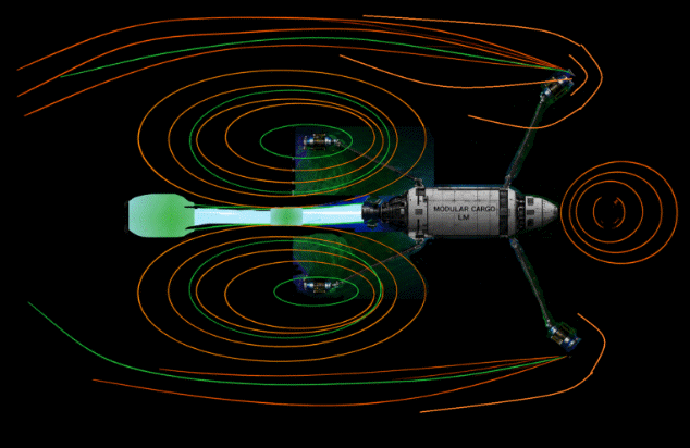
The boom-mounted shapers are arranged so that their combined fields produce an extended lobe structure around the outgoing plasma. With lobes sizes in the kilometer scale.
The field is not assumed to consist of isolated magnetic bubbles generated independently by each shaper.
Rather, the shapers establish boundary conditions for a larger coupled field:
Btotal=Bsource+i∑Bshaper,i+Bplasma.
The plasma itself therefore participates in the resulting field geometry.
This is important because the proposed lobe is not a purely prescribed vacuum magnetic field through which passive particles travel.
It is an evolving plasma-field system.
The spacecraft supplies and biases the external field, while plasma currents modify the local field and pressure structure.
The resulting geometry must ultimately be solved self-consistently.
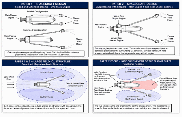
Third Diagram, Illustrative of the M2P2 design. However, the corridor shows the possibility to use in an augment second capacity. Using lobes and corridor for partial rope flux capture.
As discussed in Section 1, the magnetosphere provides a useful conceptual precedent for allowing a large magnetic-plasma structure to organize spatially rather than requiring every feature to be directly imposed by hardware.
The analogy is limited but useful.
Natural magnetized-plasma environments demonstrate that an extended interaction can develop:
lobes, boundary layers, central sheets,
and:
transport corridors.
The proposed vehicle attempts to create a much smaller engineered environment in which some analogous geometric functions occur.
It does not require dynamic similarity to Earth's magnetosphere.
The design philosophy is instead:
create the boundary conditions required for useful organization
rather than:
independently manufacture every internal plasma feature.
That distinction becomes especially important when considering the power and thermal burden placed upon the external shapers.
If the resulting lobe geometry corresponds to an accessible configuration of the coupled field/plasma system, the shapers may need primarily to bias and stabilize that configuration rather than continuously overpower its natural evolution.
That possibility remains exploratory and is examined later in the energy and boom/shaper discussions.
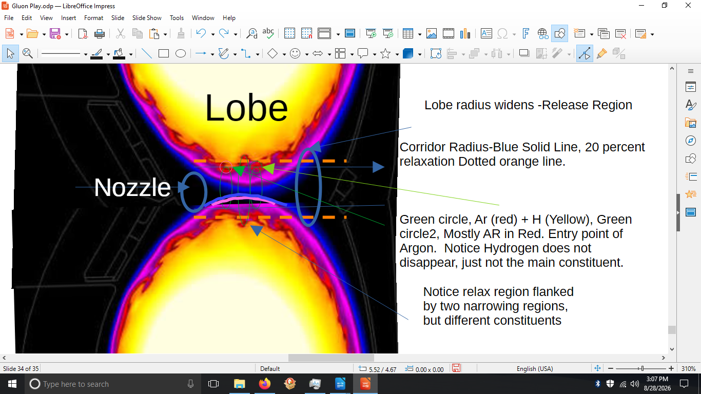
The opposing lobe geometry creates the central feature of the propulsion architecture:
the corridor.
Let its effective transverse dimension be:
Rc(z,t).
Unlike the bore of a rigid nozzle,
Rc
is an electromagnetic boundary.
Its location can therefore change without physical motion of a material wall.
In general:
Rc=Rc(z,t,B,J,p,ns,Ts).
The corridor is therefore both geometrical and dynamical.
Upstream, the lobe geometry begins to constrain and organize the injected plasma.
Further downstream, the corridor reaches a region of stronger interaction where species response, current organization, and sheet formation become increasingly important.
Beyond that region, the geometry provides sufficient space for the developing structure to persist and receive electromagnetic impulse.
Finally:
∂z∂Rc>0
in the downstream release region.
The corridor therefore has a qualitative profile:
entry→convergence→organization→acceleration→relaxation/widening.
No sharp physical boundary is assumed between these regions.
They are functions of one continuous lobe geometry.
One of the central architectural decisions is to allow the interaction region to become much longer than a conventional compact propulsion chamber.
The exact scale has not been determined.
However, the developmental concept has deliberately considered:
Lc∼102−103 m
rather than assuming that all relevant processes must occur over a few meters.
A kilometer-scale corridor should therefore be understood as a design-space scale, not an established optimum.
Its significance follows from residence time.
For a characteristic axial velocity:
vz,
the convective transit time is approximately:
τc∼vzLc.
For illustration, if:
Lc=1km
and:
vz=20km/s,
then:
τc∼0.05s.
At:
Lc=4km,
the same characteristic velocity gives:
τc∼0.20s.
These values are not predictions for the final vehicle. They demonstrate why length changes the engineering problem.
The system gains time for:
electron redistribution, H/Ar differential response, current organization, sheet formation, Maxwell-stress acceleration,
and:
progressive release.
The extended architecture therefore avoids requiring all of these processes to reach their useful state at nearly the same axial location over several meters.
For analysis, the continuous geometry can be divided into functional regions.
These regions should not be interpreted as separate physical chambers.
The plasma enters with:
m˙,vz,0,Ts,ns.
Initial species conditions are established here.
The effective corridor radius decreases:
∂z∂Rc<0.
The changing magnetic environment begins differentiating the response of electrons, hydrogen ions, and argon ions.
The interaction becomes sufficiently strong that spatially organized current and mass structures may emerge.
This is where the proposed transition:
Q2→sheet
becomes important.
A sufficiently organized but incompletely closed structure:
Q3−
remains within substantial spacecraft-field influence.
This is the principal proposed Maxwell-stress acceleration region.
The effective corridor opens:
∂z∂Rc>0.
External coupling progressively declines and the acquired axial momentum is carried downstream.
Thus:
I→II→III→IV→V
is a spatial description of the same nine-rung process developed later.
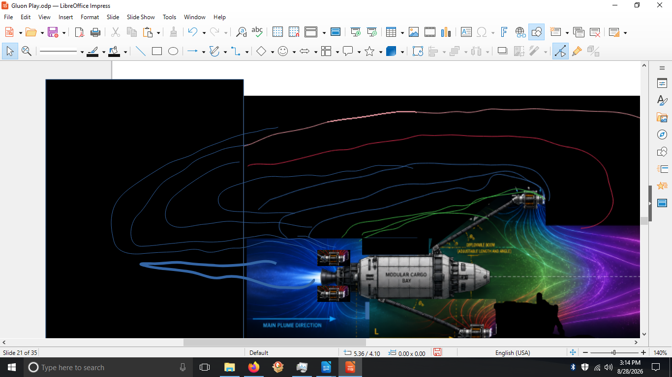
The shapers provide active control authority, but the proposal does not assume that every part of the lobe must be actively forced at every instant.
This distinction is central to the architecture.
The field system may contain both:
actively imposed geometry
and:
self-consistent plasma/field geometry.
The engineering objective would be to use the minimum necessary active intervention to keep the system within its useful operating region.
Conceptually:
natural tendency+controlled bias=desired corridor evolution.
If the plasma begins moving toward premature closure, local field geometry might be relaxed.
If the structure begins dispersing too early, local confinement could be increased.
If the desired axial release begins, the receding lobe geometry may allow the field/plasma system to open naturally rather than requiring an abrupt detachment pulse.
This is the sense in which the design attempts to adapt the field's accessible behavior rather than force a complete plasma topology at every point.
The baseline configuration can now be summarized as:
single central H/Ar plasma source↓vehicle-attached external shapers↓large coupled magnetic lobes↓extended central interaction corridor↓species differentiation and sheet organization↓externally coupled pre-Q3 acceleration↓receding-lobe progressive release.
This baseline deliberately avoids adding mechanisms not required by the central hypothesis.
It does not presently require:
a second complete propulsion engine,
a completed FRC or flux rope as the working exhaust object,
a separate mechanical release device,
solar-wind momentum for primary thrust,
or active control of every point in the extended field.
Those possibilities can be evaluated separately if the underlying corridor mechanism survives higher-fidelity analysis.
The next question is therefore what actually happens inside this geometry when electrons, hydrogen, and the small argon population respond on different characteristic scales.
That is the subject of Section 3: Species Response, Current Envelope, and Internal Plasma Structure.
The proposed corridor cannot be treated adequately as a single homogeneous conducting fluid if its operation depends upon different responses from electrons, hydrogen ions, and argon ions. Single-fluid MHD remains useful for describing much of the large-scale field and plasma behavior, but the central hypothesis specifically depends upon behavior that can become hidden when all charged populations are collapsed into one bulk velocity.
For the baseline working plasma,
H+3%Ar+e−
the relevant question is not merely whether the species separate.
It is whether their different response rates can produce a temporarily organized, quasi-neutral, current-bearing structure while the plasma remains part of the larger spacecraft-controlled lobe system.
For simplicity, consider singly ionized hydrogen and argon. Approximate quasi-neutrality requires:
ne≃nH+nAr.
Quasi-neutrality does not require the three populations to have identical velocities.
The total current density is:
J=enHvH+enArvAr−eneve.
Consequently,
vH=vAr=ve
can coexist with:
ρq≈0.
This distinction is fundamental to the proposal.
The drive does not require large macroscopic regions of uncompensated electric charge. It requires relative charged-particle motion inside an approximately quasi-neutral plasma.
That relative motion supplies current.
The masses of the participating species differ substantially:
me≪mH≪mAr.
Mass alone does not determine plasma response. Magnetization, temperature, collision frequency, charge state, density, field strength, gradients, and characteristic spatial scale all matter.
Nevertheless, the populations need not reorganize at the same rate when the corridor geometry changes.
The qualitative ordering used in the exploratory development was:
τe<τH<τAr
for the particular class of transient response being investigated.
This should be understood as a working physical hypothesis, not a universal ordering applicable to every plasma regime.
The actual relationships must be obtained from the eventual multifluid model.
What matters to the proposed mechanism is that some useful interval exists in which:
electron/current response
can reorganize faster than:
complete H/Ar mass redistribution.
That temporal separation provides the first potential mechanism for maintaining the system between simple transport and complete closure.
The small argon fraction was introduced specifically to ask whether a heavy minority population could retain a different spatial or velocity response while remaining part of the overall plasma system.
Define:
ΔvHAr=vH−vAr.
The proposal does not require:
ΔvHAr
to become extremely large.
Nor does it require permanent H/Ar separation.
Instead, it requires a nonzero differential to survive sufficiently long to influence:
local current,
mass distribution,
pressure,
residence,
and the developing pre-closure geometry.
Thus:
ΔvHAr=0
is treated as an available structural difference, not as an end state.
If collisions or collective fields immediately drive:
ΔvHAr→0,
then much of the proposed differential mechanism disappears.
That is one of the important falsification tests for the higher-fidelity model.
The electrons play a different role.
Because the plasma remains approximately quasi-neutral, differential H/Ar motion cannot be considered independently of electron redistribution.
A reduced electron momentum equation can be written:
meneDtDve=−ene(E+ve×B)−∇pe+Re.
On timescales for which electron inertia is comparatively small, this approaches the familiar generalized-Ohm-law behavior:
E+ve×B≈−ene∇pe+collisional and nonideal terms.
The electrons therefore do more than neutralize ion charge.
Their redistribution participates directly in determining:
E,J,
and consequently the electromagnetic environment subsequently experienced by both ion populations.
The interaction is therefore a feedback loop:
ΔvHAr→electron redistribution→J,E→ion response→ΔvHAr′.
This loop occurs inside a magnetic geometry that is itself evolving along the corridor.
The exploratory geometry suggests that the organized current need not occupy the same volume as the majority of the ion mass.
A useful working hypothesis is therefore an electron-dominated current envelope surrounding or partially surrounding the forming H/Ar structure.
This should not be interpreted as an electron-only shell.
Rather, it denotes a region in which the electron-ion velocity difference makes a comparatively strong contribution to:
Jorg.
Conceptually:
external lobe field ↓ electron-dominated current/transport envelope ↓ H/Ar forming-mass region.
The proposed topology remains unvalidated.
Its value at this stage is that it gives the higher-fidelity model something specific to test.
Does a coherent current-bearing layer actually develop around or across the forming mass?
If not, the conceptual picture must be changed.
Between the faster electron-dominated current region and the slower bulk-ion structure, a finite transition region is expected rather than an infinitely thin mathematical surface.
A useful diagnostic is:
Sei∼∂r∂(ve−vi).
Large values indicate a region of strong electron-ion velocity shear.
Likewise:
∂r∂J
can identify a current-gradient layer.
Within the developmental diagrams, this region was represented pictorially as part of the outer lobe envelope. The colors used in those diagrams should not be interpreted as separate electron populations.
They represent different functional regions of one coupled plasma-field structure.
For that reason, the present paper refers to the region as a:
shear/exchange layer
rather than a literal shear line.
The term exchange is intentional. Energy and momentum need not disappear there. They can transfer among:
particles,E,J,B.
The developmental framework originally distinguished transport from retention or organization.
That distinction maps naturally onto the proposed plasma structure.
The outer current-bearing region can be interpreted as providing a preferential:
transport corridor
while the shear layer provides a region of stronger:
momentum/current/energy exchange.
This does not imply that transport ceases in the exchange region or that exchange is absent elsewhere.
Rather, it identifies dominant functions.
The resulting picture is not:
plasma inside a magnetic pipe.
It is:
a spatially structured plasma whose transport properties vary across the lobe.
That distinction becomes important when interpreting the sheet.
The interior H/Ar population is likewise not assumed to be compositionally uniform.
Define the local argon fraction:
fAr=nH+nArnAr.
Even if the injected average is approximately:
fAr≈0.03,
the local value need not remain 0.03 everywhere.
Differential transport can create:
fAr(r,z,t)>0.03
in some regions and:
fAr(r,z,t)<0.03
in others while preserving the overall injected mixture.
This provides a physical interpretation for the H-rich, mixed, and Ar-rich regions that appeared in the developmental diagrams.
Define:
VO
as the substantial H/Ar overlap volume.
Then the forming structure may contain:
VH,VO,VAr
without requiring three independently closed plasma objects.
This distinction became important during the exploratory work.
An Ar-rich region extending away from the strongest H/Ar overlap was initially easy to interpret as loss.
That interpretation is incomplete.
The more important question is whether the Ar-rich population remains within the force-transmitting current/field structure.
If:
VAr⊆VJ,
then an Ar-dominant excursion may remain electromagnetically coupled even though:
VAr⊆VO.
It is differentiated, but not necessarily lost.
Conversely, if the population leaves the region of useful current/field coupling:
VAr∈/VJ,
then it becomes a genuine leakage candidate.
Thus:
species separation=propellant leakage.
The physically relevant test is:
Does the differentiated population remain inside the useful force-transfer network?
This provides a much sharper interpretation of the breakout behavior observed in the reduced models.
The internal structure can now be summarized using three principal volumes.
VM
contains the plasma mass participating mechanically in the developing pre-Q3 state:
MQ3−=∫VMρdV.
VJ
contains the current structure contributing materially to useful electromagnetic force:
Jorg.
VO
contains substantial simultaneous H and Ar participation.
There is no requirement that:
VM=VJ=VO.
Indeed, the working hypothesis is:
VM=VJ=VO,
with dynamically changing overlap among them.
This is one of the most important refinements produced by the deeper audit of the mechanism.
The distinction between VJ and VM changes the physical interpretation of propulsion.
The spacecraft field need not act uniformly and directly upon every ion in:
MQ3−.
Electromagnetic force density acts where useful current and field overlap:
fEM=Jorg×Bext.
If the strongest organized current occupies an outer region around the forming mass, electromagnetic stress can first be deposited in that region.
Collective electromagnetic and plasma stresses can then communicate momentum into the interior mass.
Schematically:
Bext→VJ→distributed plasma stress→VM.
This is more physically useful than treating the entire pre-Q3 mass as though it were a rigid magnetic body.
A corresponding coupling efficiency will later be introduced:
ηJM
to represent the effectiveness with which force deposited in the organized-current structure is communicated into the mechanically participating mass.
The conceptual vehicle diagrams developed during this study can therefore be interpreted more carefully.
The orange and red interior structures represent approximate H- and Ar-associated mass distributions and their overlap/differentiation.
The outer lobe structure represents the coupled magnetic environment and hypothesized electron-dominated current envelope.
Where different colors are used within that outer structure, they should represent:
transport/current-dominant region
and:
shear/exchange-dominant region,
not different electron species.
The diagram is therefore a structural hypothesis.
It is not a computed plasma-density, current-density, or magnetic-flux map.
That distinction should remain attached to the figure wherever it appears in the paper.
The proposed internal architecture is useful only if several things survive higher-fidelity analysis.
A multifluid treatment could show that:
H and Ar equilibrate so rapidly that no useful differential persists;
the electron response does not organize into a useful current structure;
the current structure forms but has poor spatial coupling to the H/Ar mass;
strong differential behavior produces instability or transverse loss rather than useful organization;
the hypothesized sheet does not emerge in the proposed geometry;
or the resulting electromagnetic stress is too weak or too energetically expensive to matter.
Any of these outcomes would require substantial revision of the architecture.
Conversely, the result of interest is not a visually attractive toroid.
It is simultaneous evidence of:
ΔvHAr=0, Jorg=0, VJ∩VM=∅,
and sufficient persistence for useful electromagnetic momentum transfer.
That provides the bridge to the next stage of the paper.
The proposed H–Ar mixture is not treated as a homogeneous working fluid at the scale most important to the mechanism. Differential electron, hydrogen, and argon response may permit a spatially structured plasma consisting of a forming-mass region, an organized-current envelope, a finite shear/exchange layer, and locally varying species-overlap regions.
The key progression is therefore refined from:
ΔvHAr→Jorg
to:
ΔvHAr→fast electron redistribution→current/transport organization→finite shear/exchange structure→Jorg,
while the H/Ar population simultaneously develops:
MQ3−.
The next question is whether these evolving components can become organized enough to constitute the pre-closure state suggested by the exploratory models without progressing immediately into a completed autonomous structure.
That is the subject of Section 4: Q2 → Sheet → Pre-Q3 Organization: Hypothesis and Reduced-Model Evidence.
The previous section described the proposed plasma system using conventional physical quantities: species density, velocity, current, field, mass distribution, and spatial overlap. This section introduces the developmental Q-notation used during the exploratory modeling and explains why the propulsion architecture became focused on an intermediate state rather than on production of a completed plasmoid or flux-rope structure.
The notation is intended to distinguish degrees of collective organization and persistence within the developing plasma. It is not proposed as a replacement for established MHD or plasma-state terminology.
The progression of interest is:
Q2→corridor interaction→sheet→Q3−→Q3.
The propulsion proposal seeks to operate primarily within the middle of this sequence.
Q2 represents an incoming plasma organization that possesses identifiable structure and persistence but has not yet developed the higher-order collective organization associated here with Q3.
Operationally, Q2 requires more than the mere presence of plasma.
It implies that some combination of:
flow+current+field coupling+spatial organization
already persists long enough to influence subsequent evolution.
For the proposed drive, the plasma entering the principal corridor is therefore not treated as an unstructured collection of independent particles.
It possesses an upstream state from which further organization can develop.
This distinction was important in the exploratory models because higher-order organization consistently emerged from an already structured input rather than from an assumed zero state.
The lobe corridor does not simply transport Q2.
It changes the conditions under which that state can persist.
As the effective corridor radius changes:
Rc=Rc(z,t),
the local plasma experiences changes in magnetic field, gradients, available transverse space, pressure relationships, and characteristic transport times.
Thus:
Q2(z0)
need not remain dynamically equivalent to:
Q2(z1).
The corridor can therefore be represented schematically as an operation:
Q2C(Rc,B,∇B,τ)Q2′
where C represents the combined influence of the changing corridor.
This notation does not introduce a new physical force. It summarizes the effects of the actual fields, currents, geometry, and transport acting on the plasma.
The important result is that the corridor changes what organizations are locally sustainable.
The sheet became important during the exploratory work because the transition toward greater organization did not always proceed immediately into a compact closed structure.
Instead, the developing populations could occupy an extended interaction region.
The proposed physical interpretation is that the converging lobe geometry constrains transverse transport while differential electron/H/Ar response prevents instantaneous equilibration.
The result may be an extended region in which:
Lz≫L⊥
and organized current, species overlap, and mass concentration become preferentially distributed along the corridor.
This is the proposed sheet.
The sheet should not be interpreted as an infinitely thin current sheet.
It is a finite plasma region containing internal structure.
Schematically:
current envelope⊃shear/exchange region⊃developing H/Ar organization.
Its exact topology is one of the principal unresolved properties of the proposed system.
The sheet was not introduced merely because it produced a convenient propulsion diagram.
During the exploratory model sequence, increasingly structured interactions repeatedly produced behavior that was neither simple free transport nor immediate complete closure.
Among the recurring model observations were:
spatial concentration into preferred interaction regions;
differing behavior among populations assigned different response characteristics;
finite residence within those regions;
oscillatory or breathing behavior around an organized configuration;
spatial overlap accompanied by locally differentiated populations;
breakout through weaker portions of the surrounding structure;
changing external steering authority as organization increased;
and eventual progression toward a more independently persistent configuration.
The detailed model sequence is presented in Section 11.
The important point here is the interpretation that emerged from those results:
the path toward closure possessed structure of its own.
That observation redirected the propulsion investigation.
Instead of asking only whether a completed higher-order object could be produced, the question became whether the forming state itself could be made useful.
As organization increases, the sheet begins to acquire properties not adequately described by the incoming Q2 state alone.
The developmental models suggested increasing:
residence, internal coupling, current organization,
and:
collective geometric persistence.
At some point the structure becomes sufficiently organized that it is useful to identify a participating forming mass:
MQ3−.
This does not require the structure to have reached full Q3. Defined here as a fully formed plasmoid. Which can be its own independent self sustaining structure outside of release.
The operational requirement is instead that enough mass participates coherently for long enough that the electromagnetic impulse applied during that interval can meaningfully be associated with the developing structure before coherence to the system is lost after release.
Thus:
Q3−=an identifiable, persistent, externally field coupled pre-closure state.
The minus sign is important.
It explicitly indicates:
Q3−=Q3.
Calling the state a forming mass requires care.
The proposed MQ3− is not a rigid object and does not require permanent membership of individual particles.
It is an open system.
Material can enter:
M˙in>0
and leave:
M˙out>0.
Thus:
dtdM=M˙in−M˙out.
The relevant persistence is therefore structural, not particulate.
A useful analogy is a standing flow structure: its constituent material can continually change while the organized region itself remains identifiable.
For the propulsion problem, the forming mass exists operationally when:
mass participation+current organization+geometric persistence+finite residence
remain jointly identifiable over the interaction interval.
This allows the pre-Q3 structure to receive useful impulse without requiring it to become a rigid plasmoid.
Residence is therefore inseparable from the definition of Q3−.
Let:
τJ
represent the characteristic time required for useful current organization,
τres
the persistence time of the organized region, and:
τaccel
the characteristic interval over which useful electromagnetic acceleration occurs.
The desired relationship is approximately:
τJ<τres
with:
τaccel≲τres.
A useful nondimensional screening quantity is:
Θres=τaccelτres.
The propulsion-relevant regime is approximately:
Θres≳1.
This does not establish a universal threshold. It expresses the simple physical requirement that the structure must persist long enough to receive the impulse attributed to it.
Q3 represents the higher-order closure reference used during the exploratory modeling.
Conceptually, it denotes the point at which the developing plasma structure possesses sufficiently strong internal organization and persistence that it can increasingly be treated as an entity with its own collective dynamics.
A completed FRC or coherent flux-rope-like structure provides a useful physical comparison, although Q3 is not defined as being identical to either.
The distinction is:
Q3−=forming and externally dependent,
whereas:
Q3=more strongly internally closed and independently persistent.
This distinction became particularly important when external steering was examined.
As the model structures approached stronger closure, their internal dynamics increasingly determined their subsequent behavior.
For the propulsion architecture developed here, that observation changed Q3 from the desired operating point into a reference boundary.
To make the reduced calculations numerically tractable, a normalized closure reference was required.
The study adopted:
Q3=0.70
as the working normalized reference.
This value should not be interpreted as a universal plasma constant.
It provides a numerical endpoint against which intermediate formation could be compared.
Thus a normalized state:
Q=0.35
would represent 50% of that particular working closure reference:
0.700.35=0.50.
Likewise, the model could examine behavior at fractions such as:
0.4Q3,0.6Q3,0.8Q3
without claiming that nature contains a fundamental scalar Q=0.70.
This normalization allowed the exploratory calculations to ask a much more useful question:
How much useful behavior appears before the modeled closure endpoint?
One of the uncertainties encountered during the development was that the relationship between observable organization and complete closure need not be linear.
If the forming state progressed linearly toward the adopted reference:
Q(t)∝t,
then an intermediate observation could be directly interpolated toward:
Q3=0.70.
But collective plasma organization can plausibly grow nonlinearly as coupling increases.
A generic alternative is:
Q(t)∝ekt
over some portion of the formation interval.
The exploratory calculations therefore used linear and nonlinear buildup as bounding interpretations rather than claiming either as the actual formation law.
This produced a range for the possible degree of organization associated with the observed intermediate state.
The purpose was not precision.
It was to determine whether the inferred pre-Q3 state was so small that the propulsion idea could be dismissed immediately, or sufficiently developed that further momentum-transfer analysis remained worthwhile.
The latter possibility survived that screening.
The developmental framework used the term wobble to describe the interval in which an existing organization is being sufficiently perturbed to explore another configuration while retaining enough persistence not to disperse immediately.
Within the present propulsion architecture:
Q2→corridor→sheet→Q3−→Q3
is itself the wobble process.
There is therefore no separate “wobble device” or additional instability that must be added to the architecture.
The desired operating state is a bounded transition.
At one boundary:
dispersion
destroys useful organization.
At the other:
autonomous closure
moves the structure beyond the operating region the proposed vehicle seeks to exploit.
Between them lies:
Wuseful
—the useful wobble interval.
The propulsion system attempts to remain in this interval long enough to transfer momentum.
This interpretation also changes what is demanded of the external shapers.
Their purpose is not necessarily to hold:
Q=Qfixed
at every instant.
Rather, they influence the boundaries within which the evolving plasma can move.
By changing local:
B,∇B,Rc,∂z∂Rc,
the shapers can alter confinement, curvature, transport, and the location of the transition regions.
Thus:
shaper control=microscopic plasma control.
The intended function is closer to:
control of the accessible geometric envelope.
The plasma is allowed to evolve inside that envelope.
This is consistent with the design philosophy introduced earlier: use the field's accessible organization where possible and intervene primarily to bias, maintain, or release it.
The useful wobble regime may arise because the relevant parts of the system do not respond at the same rate.
Three developmental quantities are useful for expressing this:
Jt
for temporal/state response,
JE
for energy/current transfer, and:
JL=dtdLeff
for effective geometric change.
The proposal does not require:
Jt=JE=JL.
Indeed, useful pre-closure behavior may require that they remain mismatched.
Electron/current organization may respond quickly enough to follow the changing field geometry while the heavier ion populations lag sufficiently to preserve differential structure.
The corridor itself changes on another characteristic timescale.
The qualitative operating condition is therefore:
fast enough for current organization
while simultaneously:
too dynamically mismatched for immediate complete equilibration.
This gives a possible physical basis for why the sheet can persist rather than either dispersing or immediately becoming a completed Q3 structure.
The original exploratory path treated formation of a persistent Q3-like object as an interesting result.
For a propulsion system based on ejecting completed plasmoids, that might remain the appropriate objective.
The present vehicle has a different requirement.
It seeks maximum useful organization while substantial spacecraft coupling remains.
Let:
Cship(Q)
represent the degree to which the evolving structure remains controllably coupled to the vehicle-generated field.
The useful propulsion quantity is not simply:
Q→max.
It is closer to maximizing a combined quantity:
P(Q)∼M(Q)Jorg(Q)Cship(Q)τres(Q).
This expression is schematic, not a propulsion law.
It illustrates the optimization problem.
As Q increases:
M(Q)↑
and:
Jorg(Q)↑
may be favorable.
But if:
Cship(Q)↓
rapidly near closure, then maximum formation is not necessarily maximum propulsion usefulness.
The optimum may therefore occur at:
Qoptimum<Q3.
That is the central reason for operating in the pre-Q3 regime.
The reduced models did not establish the numerical value of:
Qoptimum.
Nor did they establish the actual H/Ar/electron topology of the proposed vehicle.
Their contribution was narrower but important.
They repeatedly suggested that:
organization can develop progressively
rather than appearing only at final closure;
that:
intermediate organization can possess finite residence;
that differentiated populations can coexist with an organized larger structure;
that local breakout does not necessarily destroy the whole configuration;
that external steering can remain effective during part of the formation interval;
and that stronger closure can eventually produce behavior increasingly dominated by the resulting structure itself.
Those observations created the rationale for the pre-Q3 propulsion architecture.
Section 11 will reconstruct that modeling path in detail, including the models that proved inadequate, the interpretations that changed, and the results that survived.
We can therefore state the proposed operating interval compactly:
QM≤Q<Q3
where QM represents the minimum organization at which a meaningful participating forming mass and organized current can be identified.
Within this interval we additionally require:
τJ<τres, τaccel≲τres,
and sufficient external coupling:
Cship>Cmin.
The desired state is therefore neither weakly organized plasma nor a completely autonomous plasmoid.
It is:
organized enough to push+open enough to control.
That is probably the simplest statement of the pre-Q3 design target.
The Q2→Q3 framework provides an operational language for the developmental process that led to the proposed propulsion architecture.
The important result is not the notation itself.
It is the recognition that the transition toward a more completely organized plasma state may contain a finite interval possessing simultaneously:
forming mass, organized current, finite residence,
and:
continued spacecraft coupling.
The exploratory models suggested that this interval deserves investigation as an operating state rather than being treated merely as an inconvenient transient preceding full plasmoid formation.
The propulsion proposal therefore attempts to exploit:
Q3−
rather than requiring:
Q3.
The next section converts that developmental description into the explicit nine-rung mechanical force ladder, tracing the proposed process from differential species response through spacecraft-coupled acceleration and geometric release.
The preceding sections describe the proposed architecture geometrically and developmentally. The purpose of this section is different. Here the proposal is reduced to a mechanical chain in which every stage must connect physically to the next.
The central question is straightforward:
How does an H–Ar plasma leaving the source acquire additional axial momentum, and where does the equal and opposite reaction force return to the spacecraft?
The proposed sequence is:
1.2.3.4.5.6.7.8.9. Differential species response Lobe-defined corridor organization Identifiable pre-Q3 forming mass Organized current formation Effective spacecraft coupling Axial Maxwell stress Acceleration of an open forming structure Geometric widening Progressive coupling loss and release.
No individual rung is intended to produce propulsion independently. The proposed mechanism exists only if the chain remains connected.
The process begins with the mixed working plasma:
H+3%Ar+e−.
Because the populations have different characteristic response times, the changing corridor need not produce identical motion in all three populations.
For the ion populations define:
ΔvHAr=vH−vAr.
The propulsion mechanism does not require complete species separation.
It requires:
ΔvHAr=0
for sufficient time to contribute to the developing internal organization.
Electron redistribution responds simultaneously to maintain approximate quasi-neutrality and contributes to the resulting current.
The first rung therefore produces available internal difference, not thrust.
Rung 1 output: differential charged-particle motion.
The differential plasma enters the converging portion of the spacecraft-generated lobe.
The effective corridor dimension:
Rc(z,t)
changes along the propulsion axis.
In the converging region:
∂z∂Rc<0.
This changing geometry alters the local field and transport environment experienced by the different populations.
The lobe therefore converts an initially distributed differential into a spatially organized interaction.
Schematically:
ΔvHAr+Rc(z)+B(z)→structured transport.
This is where the sheet-like organization described in Section 4 begins to become important.
Again, this rung does not yet require a completed plasma object.
Its output is:
Rung 2 output: spatially organized differential plasma.
As residence and internal organization increase, a portion of the plasma becomes sufficiently coherent to define a forming mass:
MQ3−=∫VMρdV.
This is an important mechanical transition.
Before this point, it is sufficient to describe individual species fluxes.
After this point, the propulsion analysis can additionally ask whether a collective region receives and retains useful momentum.
The structure remains open:
M˙in>0,M˙out>0.
Thus:
M˙=M˙in−M˙out.
The forming mass is therefore not a solid projectile or permanently closed plasmoid.
It is a persistent flow structure.
The requirement is:
τres≳τaccel.
Its output is:
Rung 3 output: mechanically identifiable pre-Q3 mass.
An identifiable mass alone does not provide electromagnetic acceleration.
The next requirement is organized current.
The total current is:
J=enHvH+enArvAr−eneve.
Only the component that participates coherently in the desired large-scale interaction is represented by:
Jorg.
Random, locally cancelling, or poorly oriented currents do not contribute efficiently to the desired axial force.
The relevant condition is therefore not simply:
J=0,
but:
∫VJJorg×BextdV
having a useful axial component.
This is where the hypothesized electron-dominated current envelope becomes mechanically important.
Its output is:
Rung 4 output: force-capable organized current.
The organized current must interact with a field whose reaction can be communicated back to the spacecraft.
Let:
Cship
represent the degree of effective overlap and control between the forming plasma structure and the spacecraft-generated field.
Let:
ηJ
represent the fraction of the available current organization contributing coherently to useful force.
And let:
ηJM
represent the effectiveness with which electromagnetic stress applied in the organized-current volume is communicated into the participating mass.
Then define the working coupling measure:
Ceff=CshipηJηJM.
This is not proposed as a universal plasma coefficient.
It is an engineering bookkeeping quantity separating three physically different failure modes.
A system can have:
Cship≈1
but poor current organization:
ηJ≪1.
Or it can possess strong organized current but weak transfer into the useful mass:
ηJM≪1.
The propulsion mechanism requires all three to remain appreciable.
The output is:
Rung 5 output: spacecraft-connected force pathway.
This is the rung at which additional directed force appears.
Locally:
fEM=Jorg×Bext.
The net electromagnetic force on the relevant plasma volume is:
FEM=∫VJorg×BextdV.
The propulsion-relevant component is:
Fz=∫V(Jorg×Bext)zdV.
For useful operation:
Fz>0
in the exhaust direction.
The corresponding impulse accumulated while the structure remains coupled is:
JEM=∫t1t2Fzdt.
This quantity—not the visual appearance of the plasma—is the principal mechanical benefit sought from the pre-Q3 interval.
The output is:
Rung 6 output: additional axial plasma impulse.
The equal and opposite force does not disappear into the magnetic field.
The field-producing system is mechanically attached to the vehicle.
The reaction path is approximately:
plasma→electromagnetic field→shaper/coils→booms→vehicle structure.
Therefore:
Fship=−Fplasma
for the internally generated propulsion interaction, subject to the complete field momentum accounting.
Over the propulsion event:
Δpship=−Δpexhaust.
This is why the external booms and shapers cannot be treated as geometrical decorations. They are part of the thrust load path.
The pre-Q3 region is not a rigid body of constant mass.
Its momentum is:
pz=Mvz.
Differentiating:
dtdpz=Mdtdvz+vzdtdM.
Therefore:
Fz=Mv˙z+vzM˙
only after the control-volume boundaries and relevant mass fluxes have been specified consistently.
This matters because an increase in momentum associated with the pre-Q3 region can arise through both:
increasing axial velocity
and:
changing participating mass.
The propulsion benefit must ultimately appear in the downstream momentum flux:
p˙exhaust=∫Aρvz2dA+pressure and electromagnetic contributions.
Thus the architecture does not depend upon assigning a permanent mass to a plasmoid.
It depends upon increasing the useful downstream momentum flux.
The output is:
Rung 7 output: increased directed exhaust momentum.
The lobe eventually begins to recede from the propulsion axis.
Thus:
∂z∂Rc>0.
This geometric change performs an important function.
The propulsion architecture does not require the pre-Q3 structure to be abruptly severed from the spacecraft field.
Instead, field overlap and confinement can progressively decline as the corridor widens.
Schematically:
Rc↑→Bcoupling↓→Cship↓.
At the same time, the current-bearing envelope can expand relative to the forming mass.
Thus:
ηJM
may also decrease.
Consequently:
Ceff=CshipηJηJM
naturally falls downstream.
The output is:
Rung 8 output: progressive reduction of confinement and coupling.
Release occurs when spacecraft coupling becomes sufficiently weak that the downstream plasma carries its acquired axial momentum away from the vehicle.
Operationally:
Ceff→Crelease
where Crelease is low enough that further interaction no longer returns a substantial fraction of the acquired axial momentum to the vehicle.
Importantly, the propulsion architecture does not require the released exhaust to remain a completed toroid.
The desired conserved quantity is principally:
pz,
not:
pre-Q3 topology.
The structure may therefore expand, unwind, mix, or otherwise relax after leaving the useful spacecraft interaction region.
If its directed momentum survives:
Pz,downstream
remains useful exhaust momentum.
This is a major distinction between the proposed system and an architecture whose purpose is specifically to launch intact coherent plasmoids.
The extended corridor gives release a spatial dimension unavailable to a very short acceleration region.
In a compact device, several operations may have to occur over a relatively small distance:
formation→acceleration→field decoupling→plume establishment.
The proposed system intentionally separates these processes spatially.
If the characteristic coupling length is:
Lrelease,
then the field can taper over that distance rather than requiring an abrupt transition.
A useful geometric measure is:
ΓR=Rc1dzdRc.
Very large ΓR represents abrupt opening.
Smaller ΓR represents gradual geometric release.
The optimum value is unknown, but the architecture provides a parameter that can be adjusted through field geometry.
This is analogous in engineering spirit to replacing a step change with a taper.
Total momentum alone is insufficient.
The useful quantity is its axial component.
Define:
Pz=∫VρvzdV
and transverse momentum:
P⊥=∫Vρ∣v⊥∣dV.
A simple axial-momentum measure is:
ηaxial=Pz2+P⊥2Pz.
Likewise, a lateral-loss measure can be written:
L⊥=Pz+P⊥P⊥.
Release therefore succeeds mechanically when the corridor converts a strongly coupled pre-Q3 state into a weakly coupled exhaust while preserving a high fraction of its momentum in:
+z^.
Whether the plasma remains visually coherent downstream is secondary.
Hydrogen and argon need not leave with identical divergence.
Define characteristic plume angles:
tanθH=vz,Hv⊥,H,
and:
tanθAr=vz,Arv⊥,Ar.
An Ar-rich region that remains useful throughout the acceleration corridor can still become inefficient if its release produces:
θAr≫θH.
Thus the earlier distinction between differentiation and leakage must persist through the final rung.
The useful question remains:
Where did the momentum go?
rather than simply:
Where did the species go?
The full mechanism can now be written in one sequence:
H/Ar/e−↓ΔvHAr↓lobe/corridor organization↓MQ3−↓Jorg↓Ceff↓Jorg×Bext↓JEM↓Δpz↓Rc↑, Ceff↓↓directed released exhaust.
And the spacecraft sees the corresponding reaction:
Δpvehicle=−Δpexhaust.
That is the complete proposed mechanical ladder.
Rung |
Required process |
Mechanical significance |
|---|---|---|
1 |
Differential H/Ar/electron response |
Creates exploitable internal difference |
2 |
Lobe/corridor organization |
Converts difference into spatial structure |
3 |
MQ3− |
Establishes participating forming mass |
4 |
Jorg |
Creates force-capable current structure |
5 |
Ceff |
Connects plasma interaction to spacecraft |
6 |
J×B |
Produces axial electromagnetic force |
7 |
Variable-mass acceleration |
Converts force into exhaust momentum |
8 |
Receding lobe |
Progressively reduces confinement/coupling |
9 |
Release |
Carries acquired axial momentum downstream |
The ladder also provides a useful diagnostic feature: failure can be localized.
If the system develops a sheet but no useful current, the chain fails at Rung 4.
If it develops strong current but the current slips relative to the forming mass, it fails at Rung 5.
If strong axial impulse develops but release converts it predominantly into transverse motion, it fails between Rungs 8 and 9.
That makes the proposal experimentally and computationally divisible rather than requiring the complete vehicle to succeed or fail as a single black box.
The next section therefore examines the particularly important middle portion of the ladder—current closure, spacecraft coupling, and electromagnetic force transfer—in greater detail.
The middle rungs of the propulsion ladder contain the most important physical connection in the proposed drive. Differential species behavior and pre-Q3 organization are useful only if they produce an organized current that remains coupled to the spacecraft-generated field and if the resulting electromagnetic stress is transferred into useful axial momentum.
The proposed force path is:
species differential→Jorg→Jorg×Bext→forming mass→spacecraft reaction.
This section develops that path more explicitly.
The proposed mechanism does not depend upon maintaining large volumes of net charge.
For singly ionized hydrogen and argon:
ne≃nH+nAr.
Yet the current density remains:
J=enHvH+enArvAr−eneve.
Consequently, quasi-neutrality:
ρq≃0
does not imply:
J=0.
This is essential to the architecture.
The electrons can redistribute rapidly enough to maintain approximate charge neutrality while still possessing a velocity relative to the ion populations. The resulting current can therefore exist without requiring the plasma to become a macroscopically charged object.
An organized propulsion current cannot simply terminate inside the plasma.
Charge conservation requires:
∂t∂ρq+∇⋅J=0.
For a quasi-steady organized region:
∇⋅J≈0.
The current topology must therefore contain closure paths.
These need not resemble wires.
Closure can occur through a combination of:
axial current,
azimuthal current,
cross-field current,
electron return flow,
distributed current layers,
and currents associated with the surrounding lobe structure.
The developmental diagrams therefore should not be interpreted as showing an isolated current ribbon ending at the downstream edge of the sheet.
The hypothesized current envelope must be part of a larger closed electromagnetic structure.
This gives a more precise interpretation to the outer lobe structure introduced in Section 3.
Rather than thinking of:
VJ
as a separate current shell inserted inside a pre-existing magnetic lobe, the more natural interpretation is:
external shaper field+plasma-generated current+return-current structure=coupled lobe.
Thus:
Btotal=Bext+Bplasma.
The plasma current modifies the field that organizes the plasma.
The resulting feedback is:
B→vs→J→B′→vs′.
This is one reason the final problem cannot be represented adequately by prescribing a static magnetic field and simply tracing particles through it.
The field and plasma must eventually be solved together.
Not every current in the plasma contributes constructively to propulsion.
Write:
J=Jorg+Jlocal+Jloss.
Here:
Jorg represents current contributing coherently to the desired large-scale force;
Jlocal represents internal or locally closing currents whose net axial contribution may largely cancel;
Jloss represents current associated with leakage, unwanted oscillation, or other nonproductive pathways.
This decomposition is conceptual rather than unique.
Its purpose is to prevent the analysis from assuming that a large measured current automatically produces large thrust.
Define:
ηJ=JavailableJuseful
as a working measure of current organization.
The propulsion system seeks:
ηJ→1,
but the actual value is an engineering result.
The next distinction is equally important.
A plasma can possess a strong internal magnetic field without that field providing continued spacecraft force authority.
For propulsion, the relevant interaction is between the organized plasma current and a field whose generating structure remains mechanically connected to the vehicle.
Denote this component:
Bext.
Then the useful force density is approximately:
fuseful=Jorg×Bext.
Internal plasma-field stresses can redistribute momentum within the plasma, but they cannot by themselves provide net momentum to the spacecraft-plasma system.
The external field connection supplies the reaction pathway.
This is the mechanical reason the proposed drive deliberately operates before complete autonomous closure.
Define:
Cship
as a working measure of how strongly the relevant pre-Q3 current structure remains coupled to the vehicle-generated field.
At weak organization:
Cship
may be high geometrically, but little useful current may exist.
As organization increases:
Jorg↑.
At still greater closure, however, an increasing fraction of the structure may become governed by its own internal field topology.
Thus it is plausible that:
Cship(Q)
does not simply increase monotonically with Q.
The desired propulsion region is therefore an overlap:
Jorg large enough
while:
Cship still large enough.
This is the physical basis for the pre-Q3 operating window introduced in Section 4.
Even strong:
Jorg×Bext
does not guarantee that the majority of the useful H/Ar mass receives that momentum.
Recall:
VJ=VM.
If the organized current is concentrated primarily in an outer envelope, electromagnetic force may initially be deposited there.
The momentum must then be communicated into the mechanically participating mass.
Define:
ηJM
as the effectiveness of that transfer.
Then the force path becomes:
Bext→Jorg→electromagnetic stress→VM.
The transfer can occur through collective electric and magnetic fields, pressure gradients, particle interactions, and other plasma stresses.
A useful current envelope that simply slips around the ion mass would produce:
ηJM≪1
and little propulsion benefit.
The three coupling factors can therefore be collected into the engineering quantity introduced earlier:
Ceff=CshipηJηJM.
Again, Ceff is not a new fundamental plasma parameter.
It is a bookkeeping device.
It separates three questions:
Cship:ηJ:ηJM:Does the spacecraft field still reach/control the structure?Is the current organized usefully?Does the resulting stress accelerate the useful mass?
A strong propulsion state requires all three.
This provides a more informative design criterion than simply maximizing magnetic-field strength.
The Lorentz-force representation:
f=J×B
is useful locally.
For the larger vehicle-scale system, the same interaction can be viewed through the Maxwell stress tensor.
In magnetically dominated form:
Tij=μ01(BiBj−21δijB2).
The net electromagnetic force on a volume can be expressed through the stress crossing its boundary:
FEM=∮ST⋅ndA
with the appropriate electric-field contribution retained where required.
This representation is particularly useful for the proposed drive because the propulsion mechanism is fundamentally geometric.
The question becomes:
Does the lobe/corridor configuration create an axial imbalance in electromagnetic stress across the pre-Q3 region?
If yes:
Fz=0.
That axial stress can accelerate the plasma while the opposite reaction appears in the field-generating vehicle structure.
A perfectly symmetric field acting on a perfectly symmetric plasma structure cannot simply generate a preferred axial direction without some imposed asymmetry.
The proposed vehicle already contains that asymmetry.
The plasma has an initial axial flow:
vz,0>0,
and the corridor geometry varies along:
z.
Thus:
∂z∂B=0,
and:
∂z∂Rc=0.
The upstream and downstream magnetic environments are not equivalent.
Consequently, the developing current structure can experience different electromagnetic stresses on its forward and rearward portions.
In simplified form:
Fz∼A(PB,rear−PB,front),
where magnetic pressure is:
PB=2μ0B2.
If:
Brear>Bfront
over the relevant interacting surfaces, the magnetic-pressure difference can contribute a net downstream force.
This was one of the missing rungs identified when the proposed mechanism was compared with accelerated-plasmoid systems.
A compact plasmoid accelerator can conceptually perform:
form object→apply magnetic pressure gradient→accelerate object.
The present architecture proposes that these processes overlap.
During the pre-Q3 interval:
dtdQ>0
while simultaneously:
Fz>0.
Thus the structure is both:
forming
and:
accelerating.
This is a major architectural distinction.
The vehicle does not need to wait for:
Q=Q3
before beginning the useful momentum-transfer interval.
There is nevertheless a lower bound.
If the structure is too weakly organized, electromagnetic stress may act on disconnected plasma populations without producing a useful collective momentum increment.
This motivates the minimum formation threshold introduced in Section 4:
Q≥QM.
Above QM, a mechanically meaningful:
MQ3−
can be assigned.
The proposed useful acceleration interval is therefore:
QM≤Q<Q3.
The precise location of QM is unknown.
The earlier interpolation work attempted to establish a provisional mass scale within this interval. That calculation will be revisited in Section 8 before the illustrative velocity comparisons are made.
While:
Ceff>0,
the forming structure can accumulate electromagnetic impulse:
ΔpEM=∫t1t2Fz(t)dt.
If the initial axial momentum of the relevant plasma is:
p0,
then immediately before release:
ppre−release=p0+ΔpEM.
The corresponding vehicle impulse is:
Δpvehicle=−ΔpEM
for this added electromagnetic interaction.
The conventional plasma source reaction associated with:
p0
already acts on the vehicle through the primary propulsion system.
Thus the proposed lobe system seeks to add a second momentum-transfer interval downstream rather than replacing the initial source.
The field can transmit force, but maintaining and changing the field requires energy.
The electromagnetic energy density is:
uB=2μ0B2.
Changing the field geometry therefore changes stored electromagnetic energy.
Energy transfer through the field is represented by the Poynting vector:
S=μ01E×B.
Local transfer between fields and charged matter is represented by:
J⋅E.
Therefore the proposed additional plasma momentum must ultimately be paid for through the vehicle's energy system.
The advantage being investigated is not free energy.
It is whether the extended geometry provides a useful way to convert available electrical energy into directed exhaust momentum while reducing other vehicle-level penalties.
The external shapers require electrical supply and return paths.
Consequently, the boom architecture must carry more than structural reaction loads.
It may carry:
supply current+return current+induced current.
Time-varying plasma and field structures can produce induced electromotive force:
E=−dtdΦB.
The resulting electrical energy can:
return toward the vehicle bus,
be temporarily stored,
dissipate resistively,
couple into neighboring shapers,
or alter the local field.
Thus the complete electrical loop is potentially:
power system→shaper→field/plasma→induced response→return network.
This is the electrical counterpart of the mechanical thrust path.
The lobe geometry introduces an exploratory possibility.
If the large-scale field possesses a naturally preferred return geometry, the downstream field need not necessarily be forced directly through each shaper as though the shapers were physical pipes for magnetic flux.
Instead, the shapers may function partly as attractors or boundary conditioners that organize a larger returning field.
Conceptually:
field expands→natural return tendency→shaper-biased reorganization.
Such behavior could reduce local field gradients at the hardware and potentially distribute thermal and electromagnetic loading.
This possibility is not required for propulsion.
It is a systems hypothesis arising from treating the lobe as a coupled field geometry rather than a collection of independent coil fields.
Combining the preceding arguments suggests that useful propulsion may possess a natural intermediate maximum.
At low organization:
MQ3−↓,Jorg↓.
Near complete closure:
Cship↓
may become increasingly important.
Therefore the effective force-transfer capability could qualitatively behave like:
Fuseful(Q)∝M(Q)Jorg(Q)Ceff(Q).
Again, this is not intended as a dimensional force equation.
It illustrates the competing tendencies.
A maximum can occur at:
Qpeak<Q3.
That point would represent the condition at which the structure is sufficiently developed to behave collectively but has not yet become so autonomous that spacecraft control has substantially diminished.
This is the proposed maximum-exploitation point.
We can now sharpen the definition introduced earlier.
A propulsion-relevant Q3− state is not simply:
70%, 80%, or 90% of a finished toroid.
It is a state satisfying four simultaneous conditions:
MQ3−>Mmin, Jorg>Jmin, Ceff>Cmin,
and:
τres≳τaccel.
The exact thresholds are system dependent.
But this definition gives Q3− a mechanical meaning.
It is:
complete enough to possess useful collective mass/current
while:
incomplete enough to remain strongly vehicle coupled.
The central force mechanism requires three different forms of organization to overlap:
plasma organization +current organization +vehicle-field coupling.
Their overlap produces:
Jorg×Bext
and therefore a potentially useful axial Maxwell stress.
The mechanical path remains conventional:
plasma→field→shapers→booms→spacecraft.
The unusual feature of the proposal is where in the formation process that force is deliberately applied.
Rather than maximizing plasma closure first, the architecture seeks the intermediate condition:
Qpeak<Q3
where forming mass, organized current, residence, and spacecraft coupling overlap most favorably.
The next section examines the other quantity that determines whether this interval can actually be exploited: time—residence, rate mismatch, and the finite acceleration window available inside the extended corridor.
The proposed drive depends not only upon what structures form, but upon how long they exist relative to the processes acting upon them.
A pre-Q3 structure that possesses useful current and mass but survives for too short an interval cannot acquire significant electromagnetic impulse. Conversely, a structure that persists by rapidly progressing into an autonomous closed configuration may leave the region of strongest spacecraft control before the available interaction has been fully exploited.
The extended corridor is therefore fundamentally a time-management geometry.
Its purpose is to create a finite interval during which:
organization+residence+spacecraft coupling+axial force
coexist.
This interval is referred to here as the exploitation window.
The simplest transit time through a corridor of length Lc is:
τtransit=vzLc.
This is useful but incomplete.
Individual electrons, hydrogen ions, and argon ions can enter and leave an organized region while the region itself persists.
Thus:
τparticle=τstructure
in general.
The propulsion-relevant quantity is primarily:
τres
—the residence or persistence time of the organized structure.
This distinction allows the pre-Q3 region to behave as an open system.
Its identity does not require the same particles to remain trapped throughout the acceleration interval.
Consider the forming mass:
MQ3−(t).
Its mass balance is:
dtdMQ3−=M˙in−M˙out.
A quasi-steady organized state can therefore satisfy:
dtdMQ3−≈0
while:
M˙in=0
and:
M˙out=0.
Thus the structure can remain approximately stationary in a vehicle-relative frame even while propellant continuously passes through it.
This is an important alternative to the picture of a plasmoid that must first be created as an individual object and subsequently launched.
The proposed pre-Q3 region can instead behave more like a persistent processing structure through which mass flows.
Several timescales must be distinguished.
Let:
τe
represent characteristic electron response,
τH
hydrogen-ion response,
τAr
argon-ion response,
τJ
formation of useful organized current,
τQ
development of the larger pre-Q3 organization,
τaccel
the interval required to accumulate a meaningful electromagnetic impulse,
and:
τrelease
the characteristic downstream loss of spacecraft coupling.
The propulsion concept does not require all these quantities to be equal.
Indeed, that would largely remove the differential behavior the architecture seeks to exploit.
The exploratory interpretation suggests a qualitative hierarchy:
τe<τJ≲τres
while ion redistribution and complete closure occur on sufficiently different characteristic scales to preserve an intermediate state.
A more useful statement than imposing a universal ordering among every variable is:
τJ<τres
and:
τaccel≲τres.
The first allows useful current organization to develop.
The second allows that current structure to receive meaningful impulse before it disappears or closes into another state.
Define the residence number introduced earlier:
Θres=τaccelτres.
Then three broad regimes exist.
For:
Θres≪1,
the structure disappears too quickly for useful acceleration.
For:
Θres∼1,
formation and acceleration occur over comparable intervals.
For:
Θres>1,
the organized structure survives longer than the characteristic acceleration interval.
The proposed architecture seeks approximately:
Θres≳1.
Larger is not automatically better.
If long residence results from excessive confinement or complete closure, release may become more difficult.
This returns directly to one of the principal architectural choices.
For a compact engine:
Lc∼meters.
For the proposed vehicle-scale field:
Lc
may extend hundreds of meters or potentially kilometers.
For an approximate axial velocity:
vz,
the available convective interval grows as:
τc∝Lc.
This does not mean that a kilometer-long field automatically produces kilometer-long useful residence.
The organized region may occupy only a fraction:
Lorg<Lc.
But the vehicle gains a much larger spatial domain within which it can locate:
differentiation,
sheet formation,
acceleration,
relaxation,
and release.
The system therefore need not demand maximum field gradient and maximum plasma organization at the same physical location.
Suppose the plasma receives an additional axial velocity increment:
Δv.
If that increment occurs over interaction time:
Δt,
then the characteristic acceleration is:
aeff∼ΔtΔv.
For an approximately constant acceleration over distance La:
vf2−vi2≈2aeffLa.
Therefore:
aeff≈2Lavf2−vi2.
Increasing La permits the same velocity change to be accumulated using a smaller characteristic acceleration.
It does not reduce the kinetic-energy increment:
ΔK=21M(vf2−vi2).
The benefit is therefore not energetic magic.
It is reduced demand for an abrupt local momentum-transfer event.
The same argument can be expressed without assuming constant acceleration.
The work transferred to the plasma is:
ΔK=∫z1z2Fz(z)dz.
A short accelerator may require relatively large:
Fz(z)
over a small:
Δz.
An extended corridor can instead distribute the required integral:
∫Fzdz
over a larger distance.
This is one of the strongest engineering reasons for investigating the large lobe geometry.
The architecture trades:
highly concentrated interaction
for:
distributed interaction.
The species differential becomes useful only if it persists over a meaningful portion of this interval.
Define:
ΔτHAr=∣τH−τAr∣.
The exact usefulness of this quantity will depend upon the actual plasma regime, but conceptually:
ΔτHAr→0
reduces the available species differential.
Likewise, an extremely large separation could lead to excessive segregation rather than useful coupled organization.
The desired state therefore lies between:
immediate equilibration
and:
complete decoupling.
Again, the useful regime is intermediate.
The plasma populations are not the only parts of the system possessing characteristic rates.
The effective corridor itself can move.
Define an effective geometric coordinate:
Leff(t)
representing a relevant interaction distance—for example the position of the sheet, pinch, maximum-current region, or effective lobe boundary.
Then:
JL=dtdLeff.
Importantly:
JL=0
does not require physical motion of the booms.
The electromagnetic interaction boundary can move while the hardware remains stationary.
This provides a way of distinguishing:
hardware geometry
from:
effective plasma-field geometry.
That distinction emerged repeatedly in the reduced modeling.
The developmental analysis can therefore be represented using three broad rate classes:
Jt
for state/temporal response,
JE
for energy/current transfer,
and:
JL
for geometric evolution.
A completely static equilibrium might approach:
Jt→0,JL→0,
with steady energy transport.
The proposed pre-Q3 operating state is different.
It permits:
Jt=0,JE=0,JL=0.
The system is actively evolving while propulsion occurs.
The question is whether these rates can become bounded relative to one another.
A particularly interesting possibility suggested by the exploratory models is that persistent organization need not require all rates to vanish.
Instead, the system may approach a relationship such as:
JLJt≈bounded
or:
JLJE≈bounded
over the useful interval.
This would mean that the structure persists not because nothing changes, but because its components change in a repeatable relationship.
That is a more appropriate description for a flowing propulsion system.
The desired state could therefore be:
dtdQ3−≈0
in a coarse structural sense while:
Jt, JE, JL=0.
Mass, current, energy, and field geometry continue moving through the structure even though its larger organization persists.
The reduced models exhibited oscillatory or breathing behavior around organized states.
For the propulsion system, this need not automatically represent instability.
Let the corridor radius vary approximately as:
Rc(t)=Rˉc+δRc(t).
Likewise:
Jorg(t)=Jˉorg+δJ(t).
A bounded oscillation:
∣δRc∣<Rcrit
may simply indicate that the field/plasma structure is dynamically maintaining itself.
The relevant distinction is between:
bounded breathing
and:
growing instability.
The former may be acceptable or even useful.
The latter destroys the operating state.
The boom/shaper system introduces another characteristic frequency:
ωboom.
The sheet or pre-Q3 structure may possess:
ωsheet,
and the electrical network:
ωelectrical.
A naive design objective would be to separate all three frequencies as widely as possible.
That may ultimately be correct.
However, because the shapers actively participate in the field geometry, another possibility exists:
ωboom≈ωsheet
within a controlled operating regime.
If the phase is favorable, mechanical compliance could reduce the instantaneous work required to oppose natural field/plasma breathing.
If the phase is unfavorable, the same relationship could amplify vibration throughout the spacecraft.
Thus resonance is neither assumed beneficial nor automatically treated as a defect.
It is a coupled systems variable.
Frequency matching alone is insufficient.
Let:
ϕboom
represent boom motion,
ϕsheet
the plasma-structure breathing phase, and:
ϕE
the electrical/field-control phase.
Then useful coupled behavior depends upon:
Δϕ=ϕboom−ϕsheet.
An approximately in-phase response could reinforce desired expansion or contraction.
An unfavorable phase relationship could produce:
field opposition, structural loading,
or:
plasma destabilization.
This provides a more precise interpretation of the earlier suggestion that the boom system might be designed to “resonate” with the corridor.
The engineering target would not be resonance alone.
It would be:
bounded amplitude+controlled phase+useful energy exchange.
A changing field produces induced voltage:
E=−dtdΦB.
Therefore a breathing lobe necessarily interacts with the electrical system.
If:
ΦB(t)
oscillates, then the shaper network experiences alternating induced EMF.
Depending upon circuit design, this energy may be:
returned,stored,redistributed,or dissipated.
Thus mechanical breathing, plasma breathing, and electrical loading cannot ultimately be designed independently.
This strengthens the argument for treating the proposed propulsion system as a vehicle-level coupled system.
We can now define the proposed useful interval more clearly.
Let:
tM
be the point at which the forming structure first satisfies the minimum useful mass/current condition.
Let:
tR
be the point at which spacecraft coupling has declined to the release threshold.
Then:
Δtexploit=tR−tM.
During this interval we require simultaneously:
MQ3−>Mmin, Jorg>Jmin, Ceff>Cmin,
and:
ηaxial remains acceptable.
The available electromagnetic impulse is then:
JEM=∫tMtRFz(t)dt.
This is the quantity the extended corridor is trying to maximize.
A useful consequence follows.
Increasing confinement might increase:
τres.
But it may also:
increase field power,
increase thermal load,
encourage complete closure,
increase stored field energy,
and complicate release.
Therefore the design objective is not:
τres→∞.
Likewise it is not:
B→max.
The objective is:
max[∫tMtRFz(t)dt]
subject to acceptable energy, structure, stability, and release behavior.
This is a much more useful engineering definition of the pre-Q3 operating point.
This leads to a useful interpretation of the entire vehicle geometry.
The physical booms define space.
But the resulting lobe converts that space into available process time:
Lc→τavailable.
The species use that time differently:
τe,τH,τAr.
The current structure uses it to organize:
τJ.
The forming mass uses it to persist:
τres.
And the propulsion system uses it to accumulate impulse:
τaccel.
Thus the extended lobe is not simply a large magnetic nozzle.
It is a device for spatially arranging competing characteristic times.
That may be the clearest systems description of why the long corridor is central to the proposal.
The proposed drive depends upon a finite interval in which a forming plasma structure remains sufficiently organized and sufficiently spacecraft-coupled for electromagnetic acceleration.
That condition can be summarized as:
τJ<τres
and:
τaccel≲τres.
The useful interaction window is:
Δtexploit=tR−tM,
and the resulting electromagnetic impulse is:
JEM=∫tMtRFz(t)dt.
The long lobe corridor matters because it provides distance over which these characteristic processes can occur without requiring them to coincide at one compact axial location.
The proposal therefore uses geometry to obtain time:
extended geometry→residence→distributed force→accumulated impulse.
The next section can now put numbers around that idea. Section 8 should first reconstruct the interpolated pre-Q3 mass anchor, then develop the momentum and energy accounting, and finally use the earlier 10%, 20%, and 30% cases to show an illustrative velocity/performance envelope against the conventional plasma-engine baseline.
The preceding sections establish the proposed force pathway and the finite interval over which it may operate. This section places a provisional numerical scale on that discussion.
The purpose is not to predict vehicle performance. It is to determine whether the differences implied by the pre-Q3 architecture are large enough to matter at the systems level if the proposed coupling mechanism survives.
One clarification is important before proceeding. The developmental closure coordinate Q and the normalized participating mass are separate quantities. Full closure is represented here by:
Q=Q3
while the adopted working mass associated with the fully formed Q3 reference state is:
MQ3=0.70.
Thus 0.70 is a normalized mass reference used for the present screening calculations; it is not the numerical value assigned to the closure coordinate itself.
The reduced models suggested that the useful propulsion state occurs before complete Q3 formation.
To compare that state mechanically with a completed structure, a provisional estimate was needed for:
MQ3−.
The exploratory formation trajectory provided intermediate values of organization and participating mass, but did not directly carry the system all the way to a physically validated Q3 endpoint.
The missing portion was therefore estimated in two simple ways:
linear continuation
and:
bounded nonlinear continuation.
The purpose was to establish a reasonable range rather than select a precise formation law.
Extrapolation of the reduced formation trajectory produced a full-Q3 participating-mass range of approximately:
MQ3∼0.69−0.76.
For subsequent calculations this was simplified to:
MQ3=0.70.
A sensitivity interval such as:
0.65≲MQ3≲0.75
can later be applied without changing the gross conclusions developed below.
The 0.70 value should therefore be interpreted as a convenient center point for comparative calculations.
The reduced state/control calculation identified a representative intermediate state with participating mass approximately:
MQ3−≈0.466.
Relative to the adopted full-Q3 mass:
MQ3MQ3−=0.700.466≈0.665.
Thus the representative pre-Q3 structure already contains approximately:
67%
of the participating mass associated with the working full-Q3 reference.
This was important to the interpretation of the architecture.
The useful state is not being treated as an extremely weak precursor containing negligible mass.
It is already a substantial forming structure.
Yet approximately one-third of the eventual Q3 participating mass has not been incorporated.
For a fixed mass:
p=Mv.
An added impulse:
J
changes momentum by:
Δp=J.
If the mass is approximately settled during that interval:
Δv=MJ.
Therefore the same impulse acting on:
MQ3−=0.466
and:
MQ3=0.70
produces different velocity increments.
Their ratio is:
ΔvQ3ΔvQ3−=MQ3−MQ3≈1.50.
Thus, for equal delivered impulse:
ΔvQ3−≈1.5ΔvQ3.
This is simply ordinary momentum mechanics.
The potential value of the pre-Q3 state is not that formation creates free velocity. It is that a substantially formed current-bearing structure may be electromagnetically useful before all of the eventual Q3 mass has been accumulated.
The distinction is particularly important because the forming mass remains open.
For:
p=Mv,
the time derivative is:
p˙=Mv˙+vM˙.
Consequently, an increase in participating mass does not by itself imply acceleration.
If:
p˙=0
while:
M˙>0,
then:
v˙<0
for the simplest case.
The additional axial velocity sought by the proposed drive must therefore arise from actual momentum transfer:
ΔpEM=∫Fz,EMdt
together with the properly accounted momentum carried into and out of the open forming region.
Q3 formation provides organization.
It does not provide momentum without a force pathway.
For the pre-Q3 control volume, a useful simplified balance is:
dtdPz=Fz,EM+P˙z,in−P˙z,out.
Equivalently, for the center-of-mass representation:
MV˙z=Fz,EM+M˙H(vH−Vz)+M˙Ar(vAr−Vz)−P˙leak.
This expression reveals several distinct contributions.
Faster hydrogen entering from behind can contribute positive axial momentum if:
vH>Vz.
Slower entering argon can act as an inertial load if:
vAr<Vz.
The Maxwell-stress term provides the externally controllable contribution:
Fz,EM.
The useful propulsion result is therefore not merely an increase in M, but:
V˙z>0
and an increase in downstream axial momentum flux.
The lower pre-Q3 mass gives an acceleration advantage only if incomplete current organization still captures enough of the available Maxwell stress.
Let:
ηpre
represent the effective force-capture fraction of the pre-Q3 state and normalize the full-Q3 state to:
ηQ3=1.
Acceleration scales approximately as:
a∝Mη.
Break-even therefore requires:
0.466ηpre=0.701.
Thus:
ηpre,break−even≈0.665.
The pre-Q3 structure needs to retain only about two-thirds of the effective Maxwell-stress coupling of the completed reference structure to produce the same acceleration per unit available stress.
For a nominal 10% acceleration advantage:
1/0.70ηpre/0.466=1.10,
which gives approximately:
ηpre≈0.73.
This produces a useful screening scale.
Pre-Q3 force capture relative to full-Q3 reference |
Approximate acceleration comparison |
|---|---|
66.5% |
Break-even |
73% |
+10% |
80% |
+20% |
87% |
about +30% |
100% |
about +50% |
These values do not predict the actual coupling of the proposed plasma. They show how much coupling must survive for the lower participating mass to remain mechanically useful.
To examine the gross consequences of modest additional acceleration, consider a representative plasma-flow velocity:
v0=20 km/s.
Let the participating mass flow through the propulsion region be:
m˙=1 g/s=10−3 kg/s.
The baseline axial momentum flow is then:
p˙0=m˙v0
or:
F0=20 N.
The corresponding directed exhaust kinetic power is:
P0=21m˙v02
giving:
P0=200 kW.
This provides a simple plasma-engine comparison point.
Suppose the extended pre-Q3 acceleration region adds:
10%,20%,or30%
to the baseline exhaust velocity while mass flow remains fixed.
Then:
Illustrative case |
Exit velocity |
Total thrust |
Added thrust |
Total exhaust kinetic power |
Added kinetic power |
|---|---|---|---|---|---|
Baseline |
20 km/s |
20 N |
— |
200 kW |
— |
+10% |
22 km/s |
22 N |
2 N |
242 kW |
42 kW |
+20% |
24 km/s |
24 N |
4 N |
288 kW |
88 kW |
+30% |
26 km/s |
26 N |
6 N |
338 kW |
138 kW |
The momentum relationship is linear at fixed mass flow:
F=m˙ve.
Thus a 10% increase in effective exhaust velocity produces approximately a 10% increase in thrust at constant m˙.
Energy does not scale linearly.
Because:
Pk=21m˙ve2,
the +10% velocity case requires approximately 21% more exhaust kinetic power:
200→242 kW.
Likewise:
+20% v→+44% Pk,
and:
+30% v→+69% Pk.
This is why propulsion usefulness cannot be judged from velocity increase alone.
If the extended lobe merely accepts additional electrical power and converts it into the same incremental exhaust kinetic energy that a conventional downstream plasma accelerator could produce, then the lobe system has not yet demonstrated a fundamental efficiency advantage.
Its potential value must therefore come from the vehicle-level combination of effects:
distributed acceleration +lower pre-Q3 participating mass +continued field coupling +possible reduction of compact high-load accelerator hardware +possible reduction of gimbal and attitude-control burden +progressive geometric release.
Thus the relevant comparison is eventually not:
lobe thrustversusthruster thrust.
It is:
complete lobe propulsion vehicleversuscomplete conventional propulsion vehicle.
The normalized mass reference provides another illustrative comparison.
Take an arbitrary normalized impulse:
J=0.20.
For the representative pre-Q3 mass:
M=0.466,
the velocity increment is:
Δvpre=0.4660.20≈0.429.
For the full-Q3 mass reference:
M=0.70, ΔvQ3=0.700.20≈0.286.
Thus:
Δvpre≈1.50ΔvQ3.
The result remains qualitatively similar if the full-Q3 mass reference is varied through:
0.65−0.75.
The corresponding pre-Q3 acceleration advantage under equal force remains approximately:
1.4−1.6.
This is why refinement of the exact 0.70 reference was not necessary for the initial systems screening.
The propulsion plasma already possesses axial velocity when it enters the principal lobe interaction.
Thus the field stage adds to an existing momentum state.
For an approximately settled participating mass:
p0=Mv0.
After electromagnetic impulse:
JEM,
the momentum becomes:
p1=Mv0+JEM.
Therefore:
v1=v0+MJEM.
This is the simplest mechanical picture of the proposed downstream acceleration.
The sequence is not:
Q3−→velocity.
It is:
pre-existing flow+pre-Q3 organization+electromagnetic impulse→higher downstream velocity.
The pre-Q3 structure provides a collective current/mass state upon which the extended field can act.
Any additional velocity must be supported by an energy source.
A gross energy balance can be written:
Eplasma,in+Eelectrical,in=Eaxial,out+E⊥+Ethermal+EEM+Eradiation+Eloss.
The useful incremental kinetic energy is:
ΔKz=21M(vf2−vi2).
Electromagnetic energy transfer is related through Poynting's theorem:
∂t∂uEM+∇⋅S=−J⋅E,
where:
S=μ01E×B.
Thus the same organized current involved mechanically through:
J×B
also participates energetically through:
J⋅E.
The complete propulsion assessment must ultimately satisfy both ledgers simultaneously.
The extended architecture offers one additional systems possibility.
If the lobe is partly a naturally accessible field configuration rather than a shape that must be continuously imposed in every detail, the shapers may act more as stabilizing attractors or boundary conditioners.
A changing lobe also produces:
E=−dtdΦB
in the shaper network.
Consequently, some energy associated with local field relaxation may be:
returned to the electrical network, temporarily stored,
or:
redistributed to another shaper region.
Likewise, a geometrically favorable return field may reduce the need for each shaper to recreate the entire field independently.
If such behavior occurs, it could influence:
shaper size,
instantaneous current requirement,
thermal loading,
power-electronics sizing,
and net field-generation efficiency.
This is a speculative systems hypothesis, but it is a natural consequence of treating the lobe, electrical network, and plasma as one coupled electromagnetic system.
A modest velocity increment may become significant when integrated across an entire spacecraft architecture.
Using the illustrative:
20 km/s→22 km/s
case, effective exhaust velocity rises by 10%.
For a fixed mission velocity requirement, the rocket equation:
m0mf=e−Δv/ve
implies a lower propellant fraction as ve rises.
For an illustrative effective mission requirement:
Δv=15 km/s
and:
ve=20 km/s,
the propellant fraction is approximately:
1−e−15/20≈0.528.
At:
ve=22 km/s,
it becomes:
1−e−15/22≈0.494.
For a 100-ton departure reference, that difference corresponds to approximately:
3.3 t
of propellant.
The corresponding illustrative values are:
Effective exhaust improvement |
Approximate propellant saved on 100-t reference |
|---|---|
+10% |
3.3 t |
+20% |
6.3 t |
+30% |
8.9 t |
These comparisons become relevant because the extended boom/lobe system adds hardware mass while potentially removing or reducing other propulsion hardware.
Suppose a conventional architecture contains approximately:
2−4 t
of hardware that could potentially be eliminated or reduced through integrated lobe shaping, thrust vectoring, or simplified downstream acceleration.
At the illustrative +10% effective exhaust case, approximately:
3.3 t
of propellant is saved in the 100-ton screening example.
The allowable added lobe-system mass before gross mass breakeven is then approximately:
3.3+(2 to 4)
or:
5.3−7.3 t.
At +20%:
8.3−10.3 t
approximately,
and at +30%:
10.9−12.9 t.
Thus the boom/shaper architecture need not necessarily be extremely light to remain interesting.
It must instead justify its mass through the combined value of:
propellant reduction+displaced propulsion hardware+vehicle-system simplification.
The 10% case is particularly useful because it establishes a modest screening target.
The architecture does not need to produce a factor-of-two improvement to deserve further examination.
Under the present mass assumptions, approximately 73% of full-Q3 Maxwell-stress coupling would produce roughly a 10% pre-Q3 acceleration advantage relative to the completed structure.
At the vehicle level, an illustrative 10% exhaust-velocity improvement can already correspond to:
measurable thrust increase at fixed mass flow,
several tonnes of propellant difference on a large vehicle reference,
and enough mass margin to tolerate a substantial boom/shaper system.
Thus:
10%
is not proposed as a predicted result.
It is a useful systems relevance scale.
Below some modest improvement, the additional architecture may have little reason to exist.
At approximately this level and above, whole-vehicle trade studies become increasingly meaningful.
The back-of-the-envelope calculations produce three useful conclusions.
First:
MQ3−≈0.67MQ3
provides enough participating mass to constitute a substantial structure while preserving a potentially meaningful lower-inertia advantage.
Second:
Ceff,pre≳0.665Ceff,Q3
is sufficient for acceleration break-even under the adopted mass reference.
Third, propulsion changes of order:
10%−30%
would be large enough to affect spacecraft-level propellant and hardware trades.
What these calculations do not determine is whether the actual lobe geometry produces:
Ceff
at the required level or whether the associated power and structural costs make the result advantageous.
Those quantities belong to the architecture and system analyses that follow.
The reduced formation trajectory suggested a representative pre-Q3 participating mass:
MQ3−≈0.466,
compared with the adopted working full-Q3 reference:
MQ3=0.70.
The resulting mass ratio:
MQ3MQ3−≈0.665
creates a simple mechanical advantage: the same delivered impulse produces approximately 1.5 times the velocity increment in the representative pre-Q3 mass.
That advantage survives incomplete electromagnetic coupling provided the forming structure retains more than approximately two-thirds of full-Q3 effective force coupling.
Illustrative 10%, 20%, and 30% exhaust-velocity increments show that even modest performance changes would be significant enough to influence thrust, power, propellant, and whole-spacecraft mass trades.
The importance of the pre-Q3 architecture is therefore not that it creates momentum through formation.
It is that it may provide:
a substantial but lower-mass current-bearing still vehicle-coupled
structure over which electromagnetic impulse can be accumulated before complete closure.
The next section turns from the plasma to the hardware responsible for maintaining that interaction: the boom/shaper system as a structural, electrical, electromagnetic, and potentially resonant vehicle subsystem.
The boom/shaper system is not an auxiliary attachment to the propulsion concept. It is part of the force path, part of the electrical network, part of the field-forming geometry, and potentially part of the dynamic response of the corridor itself.
That makes it one of the places where the proposed architecture differs most strongly from a conventional compact thruster.
The boom/shaper assembly must simultaneously:
position the field +carry current +transmit thrust reaction +maintain geometric tolerances
and possibly:
participate in controlled electromechanical resonance.
The electromagnetic force acting on the plasma has an equal and opposite reaction on the field-generating hardware.
The force path is therefore:
plasma→electromagnetic field→shaper currents→boom structure→vehicle frame.
For the relevant plasma region:
Fplasma=∫VJorg×BextdV.
The corresponding vehicle reaction is approximately:
Fvehicle=−Fplasma
after the complete electromagnetic momentum balance is included.
Thus the external lobe may be spatially large and apparently detached from the spacecraft, but the reaction path is not.
The field-generating currents remain physically connected to the vehicle.
Because the shapers carry the reaction force, the supporting booms are propulsion load-bearing members.
A boom may experience:
axial loading,
bending,
torsion,
cyclic electromagnetic loading,
coil-to-coil magnetic forces,
and dynamic loads associated with field modulation.
For a shaper force:
Fs
acting at a characteristic lever arm:
rb,
a gross bending moment is:
Mb∼Fsrb.
If opposing boom loads are symmetric, transverse components may approximately cancel while useful axial components add.
If they become asymmetric, the same system can produce:
T=i∑ri×Fi,
creating a spacecraft torque.
That torque may ultimately be either a control resource or a disturbance.
A conventional compact propulsion system often introduces thrust into the spacecraft through a relatively concentrated thrust frame or gimbal structure.
The lobe architecture offers a different possibility.
With multiple boom roots arranged around the vehicle:
Fthrust=i∑Fz,i.
The total propulsion reaction can therefore be distributed among several structural attachment points.
This may reduce the peak load at any one interface.
The trade is that boom stiffness and positional accuracy become directly coupled to propulsion performance.
If a boom deflects:
δrb,
the shaper location changes.
That modifies:
Bext(r,z),
which can alter:
Rc,Jorg,Ceff,
and consequently the electromagnetic force that produced the deflection.
Thus:
field force→boom deflection→field change→plasma response→field force.
The boom system is therefore part of a coupled electromechanical feedback loop.
A useful geometric distortion parameter is:
ϵb=Rcδrb.
The acceptable value of:
ϵb
will depend on how sensitive the corridor is to shaper placement.
This tolerance is presently unknown.
Each active shaper requires a complete electrical circuit.
A simplified path is:
power electronics→supply conductor→shaper→return conductor→power electronics.
No deliberate current may simply terminate at the end of a boom.
In a quasi-steady conductor:
∇⋅J≈0.
The boom system must therefore include explicit supply and return current paths.
This requirement affects:
conductor placement,
magnetic self-fields,
electromagnetic interference,
thermal design,
insulation,
and mechanical loading.
The current carried along a long boom is itself magnetically active.
A boom conductor carrying:
Ib
in the presence of local field:
B
experiences force per unit length:
dldF=Ibdl×B.
Thus the boom-current routing cannot be designed independently of the lobe geometry.
Supply and return conductors may be arranged to reduce unwanted external field components and minimize net boom torque.
For example, closely paired counterflowing conductors can reduce some far-field magnetic contributions.
However, the final geometry must account for:
Bshaper, Bboom,
and:
Bplasma
simultaneously.
The boom electrical network also receives energy from the changing electromagnetic environment.
For magnetic flux:
ΦB
linked by a shaper circuit:
Eind=−dtdΦB.
Thus a breathing or translating plasma structure can induce voltage in the shaper system.
This creates a bidirectional energy pathway:
power system→shaper→field/plasma
and:
changing field/plasma→shaper→electrical network.
The latter does not automatically constitute useful energy recovery.
Its usefulness depends upon the circuit topology and phase relationship.
Induced electrical energy may follow several paths.
It may be:
dissipated
as resistive or switching loss;
stored
in inductive, capacitive, or other energy-storage elements;
returned
to the spacecraft DC bus;
or:
redistributed
to another shaper section.
The last possibility is particularly relevant to an extended multi-shaper system.
If one region of the field is relaxing while another is strengthening, an actively switched network could in principle transfer part of the electrical energy between them.
Conceptually:
relaxing shaper→shared electrical bus/storage→energizing shaper.
This is a conventional circuit-level possibility applied to an unusual geometry.
Two forms of recirculation should be distinguished.
The large-scale magnetic structure may possess a preferred return geometry determined by the coupled field and plasma.
Electrical energy induced or recovered in one shaper circuit may be returned to the vehicle network or another shaper.
They are not the same process.
But they can interact.
A changing field produces induced electrical response, and the electrical response can subsequently alter the field.
Thus:
lobe→shaper→electrical network→shaper→lobe.
This closed feedback path is one of the potentially useful characteristics of treating the lobe as a vehicle-scale integrated electromagnetic system.
One speculative systems possibility deserves explicit separation from the core mechanism.
If the desired lobe configuration lies near a naturally accessible configuration of the plasma-field system, the shapers may not need to independently impose every field contour.
They may instead provide:
bias,boundary conditioning,phase control,stabilization.
In this picture the shaper acts more like an attractor for the desired field geometry than a device that continuously forces the entire lobe against its preferred configuration.
The potential consequences are important:
lower instantaneous shaper current,
lower local heat generation,
smaller shaper hardware,
reduced switching burden,
and more distributed field-energy storage.
This remains a hypothesis.
But it represents one reason the extended geometry could have systems value beyond simply producing a larger magnetic field.
The boom structure possesses natural mechanical modes:
ωb,1,ωb,2,…
The sheet/lobe system may possess its own characteristic oscillations:
ωsheet.
The usual conservative design approach would avoid:
ωb≈ωsheet.
For the proposed architecture, that may not always be the optimal choice.
If the plasma naturally produces bounded breathing, a carefully selected boom mode could potentially follow that breathing with reduced active-control effort.
Thus:
ωb≈ωsheet
could be intentionally considered.
The key word is controlled.
Matching frequency alone can produce either beneficial or destructive behavior.
Let:
ϕb
be the boom displacement phase and:
ϕs
the sheet/lobe breathing phase.
Then:
Δϕ=ϕb−ϕs.
A favorable phase could:
assist corridor opening and contraction,
reduce instantaneous shaper effort,
and store/return some mechanical energy.
An unfavorable phase could:
drive corridor instability,
increase shaper loads,
generate large vehicle vibration,
and destroy the intended field geometry.
Thus the engineering condition is more like:
ωb∼ωsheet,Δϕ∼Δϕuseful,Ab<Amax.
The electrical network introduces another characteristic frequency.
For a simplified inductive-capacitive shaper network:
ωLC=LC1.
This creates the possibility of three coupled modes:
ωsheet,ωboom,ωLC.
A tuned system might intentionally place them in a useful relationship.
For example:
ωsheet∼ωboom∼ωLC.
In that case energy could circulate among:
plasma↔field↔electrical network↔mechanical structure.
The external power system would still provide net propulsion energy and replace losses.
The potential benefit would be reduced energy repeatedly spent fighting the system's own natural oscillation.
The same possibility is also a major risk.
A lightly damped coupled mode could produce:
field oscillation→boom motion→larger field oscillation.
That is a positive-feedback path.
The design would therefore require controlled damping:
ζ>0
and limits on:
Ab,δB,δRc.
Thus the proposal is not to maximize resonance.
It is to determine whether controlled compliance and phase-tuned response offer a better systems solution than attempting to make the entire boom/shaper system infinitely rigid.
If the outer propulsion system is intentionally compliant, the central spacecraft should not necessarily share that motion.
A mechanical architecture could therefore include:
shaper→responsive boom→isolation interface→vehicle frame.
This separates two structural objectives:
Allowed to move within controlled limits.
Kept relatively quiet for:
payload,
docking,
reactor,
power electronics,
sensors,
and avionics.
The isolation system must still transmit the required net thrust.
Thus it must attenuate oscillatory loads without eliminating the mean propulsion reaction.
The baseline vehicle uses one integrated propulsion architecture rather than duplicating the entire lobe engine.
Redundancy is therefore sought internally.
Possible segmentation includes:
multiple shaper coils +multiple power channels +multiple plasma-feed/ionization channels +reconfigurable field control.
If one shaper section fails, adjacent sections could potentially alter their currents to maintain a degraded but usable lobe.
This is more consistent with the coupled geometry than attempting to install a completely independent second engine.
A useful reliability target is:
component failure→reduced field quality
rather than:
component failure→complete propulsion loss.
The degree to which this is possible will depend upon how sensitive the corridor is to individual shaper locations and currents.
This suggests a future field-control problem:
minRcdamaged(z)−Rcdesired(z)
subject to the remaining available shapers.
The architecture therefore lends itself naturally to graceful degradation if sufficient control redundancy exists.
The boom/shaper system produces heat through:
conductor resistance,
switching loss,
eddy-current loss,
magnetic-material loss where applicable,
radiation absorption,
plasma interaction,
and structural damping.
A distributed architecture may help because the heat-producing hardware is physically spread over a large area.
If field-energy recirculation reduces continuous shaper forcing, thermal loading could decrease further.
The relevant quantity is ultimately:
Pthermal=Pelectrical,in−Precovered−Pfield/plasma,useful.
This energy must be rejected through the spacecraft thermal system.
Thus any claimed reduction in shaper power would have direct implications for radiator mass.
The proposed architecture should not be described simply as “simpler” than a conventional plasma thruster.
A more accurate comparison is:
less mechanically articulated
but potentially:
more electromagnetically integrated.
Potentially reduced components include:
large gimbal mechanisms,
multiple articulated thruster heads,
some attitude-control propulsion,
and perhaps some dedicated compact acceleration hardware.
Potentially increased complexity includes:
long deployable booms,
large distributed current paths,
multiple shaper circuits,
field sensing,
coupled plasma-field control,
and electromechanical resonance management.
The trade therefore occurs between mechanical concentration and distributed electromagnetic integration.
The boom/shaper system closes both the mechanical and electrical loops required by the propulsion proposal.
Mechanically:
plasma force→field→shaper→boom→spacecraft.
Electrically:
power system→shaper→field/plasma→induced response→return network.
The architecture further permits, but does not require, a more complex operating mode in which the boom, electrical network, and plasma sheet occupy intentionally related dynamic frequencies.
This could allow some oscillatory energy to be stored, returned, or redistributed rather than continuously dissipated.
The same coupling creates substantial stability and vibration risks.
The boom/shaper system should therefore be treated as an integrated structural-electrical-electromagnetic subsystem, not simply as a support frame for external magnets.
The next section follows the plasma to the end of that system and examines release geometry, corridor length, and the preservation of useful axial momentum as spacecraft coupling declines.
The release region is not an afterthought in the proposed architecture. It is the downstream continuation of the same lobe geometry that created the corridor, organized the plasma, and enabled the pre-Q3 acceleration interval.
This matters because the vehicle does not seek to form a completed plasmoid inside a short chamber and then solve a separate detachment problem. The baseline proposal instead attempts to stop at the point of maximum useful organization while spacecraft coupling remains strong, then allow that coupling to decline progressively as the lobe naturally recedes.
The intended sequence is:
Q2→sheet→Q3−→useful acceleration→decreasing confinement→release.
The architecture therefore treats formation, acceleration, and release as one continuous geometric process.
During formation, two useful quantities initially increase together:
internal organization↑
and:
participating mass/current coherence↑.
At low organization, the plasma does not possess enough collective mass, current, or residence for the external field to act upon efficiently.
Continued organization is therefore useful.
But only up to a point.
As closure progresses, an increasing fraction of the structure can become governed by its own internal current and field topology rather than by the spacecraft-imposed geometry.
Thus:
dQdS>0
for internal organization S, while near stronger closure:
dQdCship<0.
The propulsion objective is therefore not:
maxQ.
It is:
max[useful organization×spacecraft control].
A simple illustrative representation is:
S(q)=q, Cship(q)=1−qn,
with:
q=Q3Q.
Then a crude usefulness measure becomes:
U(q)=q(1−qn).
At:
q=0,
there is little useful structure.
At:
q=1,
there is maximum closure but minimal external authority in the limiting representation.
Therefore:
0<qpeak<1.
This is the mathematical statement of the design principle:
maximum useful organization, not maximum organization.
Within the developmental framework, Q3 closure means more than simply increasing a scalar measure of organization.
A completed Q3 has acquired enough internally retained relationship to persist as its own structure.
Schematically:
Q2+Δ+transport+constraint→Q3.
Before closure, the developing structure remains substantially conditional on the Q2 environment and the spacecraft-generated corridor.
After sufficient closure:
Q3≡Q2.
It has become a new persistence.
In framework terms:
Q3→Qi′.
That is normally an important emergence result.
For this propulsion application, however, it can become an engineering burden.
The spacecraft does not need to create another long-lived object.
It needs to transfer momentum to exhaust.
Thus the desired state is:
Q3−
where the structure is complete enough to possess:
forming mass,
organized current,
residence,
coherent force transfer,
but remains incomplete enough that the spacecraft still exerts substantial influence.
The reduced models did not establish a calibrated physical law:
Cship(Q).
They did, however, suggest a recurring qualitative pattern.
As organization increased, the modeled structures showed increasing:
residence,
internal coupling,
geometric coherence,
and higher-order persistence.
At the same time, the behavior increasingly appeared to be governed by the emergent structure itself rather than by the original external steering conditions.
That changed the propulsion interpretation.
The result of interest was no longer merely:
Q3 can form.
It became:
there is an interval before Q3 where useful structure exists and external control still remains.
That interval became the propulsion target.
A fully formed plasmoid is not inherently undesirable.
For a propulsion system designed specifically to form and launch coherent plasmoids, strong closure may be advantageous.
But once the structure becomes substantially self-organized, the spacecraft is interacting with:
an electromagnetic object
rather than simply shaping:
an externally dependent plasma flow.
The vehicle must then accomplish some combination of:
continued acceleration,
guidance,
stabilization,
field separation,
and detachment.
This is a legitimate propulsion strategy and one pursued in FRC/plasmoid research.
The present architecture asks a simpler question:
If full closure is not required to obtain useful momentum transfer, why voluntarily inherit the extra control and detachment burden?
The answer proposed here is:
stop forming when the propulsion task has enough structure to work with.
The force-transfer discussion can be summarized using:
Π(Q)=M(Q)ηJ(Q)ηJM(Q)Cship(Q).
This is not a thrust equation.
It represents the overlap of the conditions needed for useful force transfer.
During early formation:
M(Q)↑, ηJ(Q)↑.
Near stronger closure:
Cship(Q)↓
may become increasingly important.
Thus:
Π(Q):0→maximum→decline.
Define:
Qexploit=Q<Q3argmaxΠ(Q).
Operationally, this is the useful:
Q3−
state.
The system should begin transitioning toward release once further closure adds less propulsion value than the external authority it costs.
The architecture can only exploit this intermediate state if there is enough distance and time between weak organization and full closure.
That is where the extended corridor becomes essential.
A compact engine may need to accomplish:
injection→formation→closure→acceleration→detachment
over a comparatively short distance.
The present architecture intentionally spends distance.
Let:
Lc
represent the total useful corridor length.
Conceptually:
Lc=LF+LA+LR,
where:
LF
is the formation/organization region,
LA
the principal acceleration region,
and:
LR
the progressive release region.
No physical wall separates them.
They are spatial functions of one continuous lobe.
For characteristic axial velocity:
vz,
the available transit time is:
τc∼vzLc.
If:
Lc=1 km
and:
vz=20 km/s,
then:
τc∼0.05 s.
At:
Lc=4 km,
the same velocity gives:
τc∼0.20 s.
These values are illustrative, but they show the purpose of vehicle scale.
The corridor provides time for:
electron redistribution,
H/Ar differential response,
current-envelope organization,
forming-mass residence,
Maxwell-stress acceleration,
and controlled loss of coupling.
Thus:
geometry→available process time.
Suppose the structure receives an additional:
Δv
over acceleration length:
LA.
For a gross constant-acceleration estimate:
a≈2LAvf2−vi2.
Increasing LA reduces the local acceleration required for the same velocity increment.
The energy requirement remains:
ΔK=21M(vf2−vi2).
Thus the long corridor does not remove the energy cost.
It distributes the momentum-transfer process over a larger spatial interval.
That is one of the principal advantages being investigated.
The desired sequence is not:
accelerate completely→switch field off.
It can instead be:
accelerate→begin widening→continue reduced acceleration→release.
Thus the end of the acceleration region and beginning of the release region can overlap.
The downstream widening helps arrest further closure while some useful external force remains.
This gives:
Q3−→widening
before:
Q→Q3.
The geometry therefore helps prevent the system from forming more persistence than the propulsion task requires.
In the organizing region:
dzdRc<0.
Downstream:
dzdRc>0.
As the plasma moves with:
vz>0,
it experiences:
dtdRc=vzdzdRc
for a steady field geometry.
Thus the spatially receding lobe automatically produces a time-dependent reduction of confinement for the moving plasma.
No separate mechanical release device is required in the baseline concept.
Let:
Ceff(z)
represent the effective force-transfer coupling.
A desirable release profile satisfies:
dzdCeff<0.
Conceptually:
Ceff:1→0.8→0.5→0.2→0.
At the same time:
Rc↑.
The same geometry can reduce:
Cship
and:
ηJM,
because the current envelope and participating mass increasingly cease to occupy the same tightly controlled volume.
Thus:
Ceff=CshipηJηJM→0.
Release follows naturally from the loss of overlap.
Define:
ΓR=Rc1dzdRc.
Large ΓR corresponds to abrupt widening.
Small ΓR corresponds to gradual release.
A long corridor permits the coupling and geometry to taper over a larger distance.
This may reduce:
sudden transverse expansion,
reflection,
field ringing,
current disruption,
and abrupt loss of organization.
The lobe therefore behaves conceptually like a magnetic impedance taper.
The optimum taper is not known, but the architecture gives the vehicle room to create one.
A short plasmoid engine can potentially form and accelerate a completed coherent structure very efficiently.
But it must solve several transitions rapidly:
formation+closure+acceleration+detachment+plume establishment.
The extended architecture spreads these functions apart.
It trades:
compactness
for:
interaction length.
That may reduce the need for large local field gradients and abrupt detachment transitions.
It also increases:
structural size,
field-control complexity,
and boom/shaper requirements.
The proposal therefore does not claim that longer is inherently superior.
It proposes that length is an engineering resource that may simplify the plasma-state transitions sufficiently to offset the cost of the larger vehicle architecture.
Before release:
MQ3−, Jorg,
and:
Ceff
matter because they enable force transfer.
After release, the principal quantity of interest is:
Pz.
Thus:
preserve momentum, not necessarily topology.
The released structure may:
expand,
unwind,
mix,
lose the sheet,
lose the current envelope,
or fragment.
These outcomes are acceptable if:
Pz,downstream
remains high.
This is another reason the architecture does not require full Q3 closure.
A long-lived downstream object provides no propulsion advantage merely because it survives.
Let:
Pz,R
be axial momentum entering the release region and:
Pz,∞
the useful far-downstream axial momentum.
Define:
ηR=Pz,RPz,∞.
The desired limit is:
ηR→1.
A low value means the release process gives back or redirects a significant portion of the acquired axial momentum.
Write:
Pz
for axial momentum and:
P⊥
for transverse momentum.
Define:
ηaxial=Pz2+P⊥2Pz
and:
L⊥=Pz+P⊥P⊥.
The release succeeds only if the widening lobe does not simply convert organized axial flow into radial expansion.
The downstream lobe therefore remains part of the propulsion system until:
Ceff
has become negligible.
Hydrogen and argon need not exhibit the same divergence.
For each species:
tanθs=vz,sv⊥,s.
Thus:
θH
and:
θAr
should be tracked separately.
An Ar-rich excursion that remains inside the useful current envelope during acceleration is not automatically leakage.
But if it exits with:
θAr≫θH,
much of its acquired momentum may cease to contribute efficiently to axial thrust.
The relevant question remains:
where does the momentum go?
rather than merely:
where does the species go?
A species-dominant region inside the central corridor is not necessarily released.
If:
VAr⊂VJ
and:
Ceff>Crelease,
it remains part of the force-transmitting system.
True release occurs when the relevant electromagnetic connection falls below the level required to materially change the exhaust momentum.
Thus:
species separation=release.
And:
spatial breakout=propellant loss.
The controlling quantity is force-transfer coupling.
Define:
Pz,+
as forward axial momentum and:
Pz,−
as backward-directed momentum.
Then:
RP=Pz,+Pz,−.
A useful release has:
RP≪1.
Backflow is undesirable because it can:
reduce thrust,
increase upstream plasma interaction,
heat the boom/shaper system,
disturb the formation region,
and couple the exhaust back into the sheet dynamics.
The long release geometry may help by making the transition less abrupt.
The wobble regime is:
Q2→sheet→Q3−.
The downstream lobe changes the conditions that supported continued closure.
As:
Rc↑,
confinement falls.
As:
Ceff↓,
the spacecraft stops imposing the same structure.
Thus instead of completing:
Q3−→Q3,
the system can transition:
Q3−→relaxing directed exhaust.
The useful wobble interval therefore ends through geometric release, not necessarily through completion of the next persistent state.
The release philosophy can now be stated more precisely.
The proposed system seeks field/plasma configurations that are dynamically accessible under the imposed boundary conditions and then biases their evolution toward useful momentum transfer.
Thus:
accessible field/plasma tendency+controlled geometric bias→useful propulsion trajectory.
The vehicle does not attempt to prescribe every intermediate topology.
Nor does it require the plasma to become more organized than necessary.
This gives the architectural principle:
form only as much persistence as the task requires, then use geometry to let it go.
A successful release should satisfy:
Ceff→0
smoothly;
ηR→1
for momentum retention;
L⊥≪1
for low transverse loss;
RP≪1
for low backflow;
and acceptable:
θH,θAr.
No success criterion requires:
Q→Q3
or preservation of a downstream toroidal object.
The proposed drive does not stop short of Q3 because complete plasmoid formation is considered impossible or undesirable in general.
It stops short because the propulsion objective is different.
Increasing organization initially improves:
M,Jorg,τres.
But approaching autonomous closure can reduce:
Cship.
The useful operating condition is therefore an intermediate maximum:
Qexploit<Q3.
The extended corridor makes that strategy physically meaningful because it provides distinct spatial regions for:
formation→acceleration→release.
The downstream lobe then widens naturally:
dzdRc>0,
reducing confinement and force-transfer coupling until:
Ceff→0.
The desired output is not a completed persistent plasmoid.
It is:
directed downstream momentum.
That now integrates the why not full Q3, the framework interpretation, the toy/control result, the kilometer-scale corridor argument, and the actual release mechanics into one coherent section.
The proposed architecture did not appear fully formed at the beginning of the study. It emerged through a sequence of increasingly specific reduced models, toy systems, geometric interpretations, and later corrections.
This history matters because several ideas that became important to the final proposal were not original assumptions. They appeared only after earlier interpretations proved incomplete or after a model produced behavior that redirected the investigation.
The purpose of this section is therefore not to present the exploratory models as proof of the propulsion system. It is to document the developmental evidence path:
question→toy/reduced model→observed behavior→interpretation→revision of the architecture.
The resulting propulsion proposal should be read in that context.
The initial objective was broader than the final H–Ar propulsion architecture.
The exploratory work investigated whether interacting transport structures could produce:
persistent regions,
organized manifolds,
residence,
breathing or oscillation,
higher-order closure,
and eventually new collective structures not explicitly imposed in the initial conditions.
A recurring question was whether several individually defined regions or populations could develop a new organizing relationship:
Qi→Q2→Q3
without prescribing the final geometry in advance.
This emphasis is important.
The models were originally intended to ask:
What does the system produce if local transport, persistence, and coupling are allowed to interact?
The propulsion interpretation came later.
One of the first useful recurring behaviors was finite residence.
Particles or walkers entering selected regions did not simply pass through once, nor did they necessarily become permanently trapped.
Instead, some regions exhibited:
entry→finite residence→exit→return.
This was important because it suggested a third behavior between:
free transit
and:
permanent capture.
In one representative breathing/residence study, the number of walkers reaching the selected right-lobe region increased from approximately 145 to 173 as the model evolved. The return fraction increased from approximately 0.855 to 0.925, while mean continuous residence increased from approximately 0.973 to 1.079 in the model's normalized units. At the same time, the longest individually trapped trajectory disappeared.
The useful interpretation was not permanent confinement.
It was:
renewable finite residence.
Material could continually enter and leave while the region itself remained dynamically important.
That observation later became central to the pre-Q3 forming-mass concept.
The same model family also suggested that persistent organization need not be static.
Selected regions alternately strengthened and relaxed while preserving a recognizable larger structure.
This was described as:
breathing
or:
wobble.
Initially, oscillation could have been interpreted simply as imperfect convergence toward a stable state.
The subsequent framework interpretation was different.
A persistent structure could remain identifiable while:
R(t),J(t),M(t)
continued to vary.
This supported the later idea that the desired propulsion state might be:
bounded nonequilibrium
rather than:
static equilibrium.
That distinction ultimately became the basis for interpreting the entire:
Q2→sheet→Q3−
interval as the wobble regime.
As coupling was increased in later toys, the models began producing structures with stronger:
internal organization,
persistence,
geometric relationship,
residence,
and reduced dependence upon the initial individual components.
This motivated the Q3 terminology.
The key question became:
Has a new invariant or persistent relation appeared that none of the original components possessed individually?
This was a more stringent criterion than simply observing a high-density region or temporary overlap.
The models suggested that sufficiently coupled Qi structures could eventually behave collectively enough to justify treating the resulting organization as a new higher-order persistence.
At that stage, producing Q3 was considered an important success.
For the later propulsion work, however, Q3 became more useful as a reference endpoint than as the desired exhaust state.
Some of the later models produced structures interpreted as rope-like, tubular, or toroidal.
These results initially encouraged comparison with:
flux ropes,
field-reversed configurations,
and other coherent plasmoid structures.
That comparison was useful because it suggested that the modeling framework could generate organization resembling known classes of magnetized plasma structures.
However, the interpretation was later narrowed.
The reduced models did not establish that a physically correct FRC or flux rope had been produced.
They established that:
greater closure could produce a more self-consistent collective object.
That distinction is important to the present paper.
The eventual propulsion architecture does not depend upon claiming that the toy generated an actual FRC.
A particularly important conceptual transition occurred when the increasingly coherent structures were subjected to external steering or field changes.
Earlier, less-closed structures responded strongly to the imposed external geometry.
As organization increased, the system increasingly appeared to retain its own internal relationship.
This suggested a qualitative control trade:
internal coherence↑
while:
external steering authority↓.
The models did not establish a calibrated function:
Cship(Q).
But they were sufficient to raise the engineering question:
If a more completely closed plasma structure is increasingly governed by its own retained topology, why wait until full closure before trying to obtain useful propulsion?
This was one of the major redirections of the study.
Once that question was raised, the focus changed.
The objective was no longer simply:
form Q3.
Instead:
identify the most useful state on the way to Q3.
This produced the operational concept:
Q3−.
The desired state needed enough organization to possess:
participating mass,
organized current,
finite residence,
coherent force transfer,
while retaining substantial interaction with the external field.
This was the point where the framework began turning into a propulsion architecture.
The next important development was to stop treating the plasma populations as dynamically identical.
Hydrogen and a small argon fraction were used as a simplified differential pair.
The purpose was not detailed plasma chemistry.
It was to examine whether two ion populations with substantially different masses could remain:
coupled
without becoming:
dynamically identical.
Reduced corridor models suggested that useful differential behavior could persist over finite interaction lengths.
A key result from those explorations was that maximum confinement was not automatically best.
Moderate corridor shaping could preserve or increase the useful H–Ar difference, whereas excessive collapse tended to erase or distort the behavior being sought.
That result strongly influenced the final architecture.
The corridor became:
controlled finite radius
rather than:
maximum pinch.
At one point, the investigation began drifting toward modulating the external shapers simply to observe what resulting plasma behavior appeared.
That was corrected.
The intended control objective was restored to:
use the shapers specifically to create favorable conditions inside the corridor.
The lobe system was therefore no longer interpreted as an independently interesting magnetic structure.
Its purpose was:
define corridor radius,
establish local pressure and field gradients,
control where species overlap,
maintain the sheet/pre-Q3 state,
and eventually produce natural downstream release.
This correction was important because it brought the modeling back to the original vehicle geometry.
The differential-species models also suggested that local composition need not remain uniform.
Some regions showed stronger overlap.
Others behaved more independently.
This was interpreted through the idea of:
H/Ar overlap regions
and:
Ar-dominant breakout regions.
Initially, breakout could easily be interpreted as leakage.
Later, after the current-envelope concept was developed, the distinction became sharper.
A species-dominant excursion does not necessarily represent loss if it remains within the larger force-transmitting electromagnetic structure.
Thus:
species separation=mechanical decoupling.
This reinterpretation ultimately produced the spatial distinction:
VM=VJ=VO.
The propulsion study became substantially more coherent when electron behavior was no longer treated as merely a neutralizing background.
Previous exploratory work had already indicated a strong separation between fast electron/toroidal response and slower ion-associated response.
This suggested that the electron population could reorganize on a timescale much shorter than the ion mass distribution.
That led to the present hypothesis of:
electron-dominated current organization
surrounding or intersecting:
slower H/Ar forming mass.
The present paper's current-envelope and shear/exchange-layer interpretation arose from this line of reasoning.
Again, the exact geometry has not been produced by a complete multifluid calculation.
What survived from the exploratory work was the importance of timescale separation.
The developmental diagrams used different colors to represent the outer lobe structure and the interior H/Ar populations.
These were later interpreted more carefully.
The outer colors were not taken to represent separate electron species.
They were instead assigned possible functional meanings:
electron/current transport region
and:
electron-ion shear/exchange region.
This produced a nested working picture:
external lobe ↓ electron-dominated current envelope ↓ shear/exchange layer ↓ H/Ar forming mass.
That picture is now used as a hypothesis diagram rather than as a calculated plasma map.
Another result that survived the exploratory work was that time, energy transfer, and geometry could not always be treated as interchangeable variables.
Three developmental quantities were introduced:
Jt
for temporal response,
JE
for energy/current transfer,
and:
JL=dtdLeff
for effective geometric change.
The models suggested that useful organization may arise precisely because these rates do not equilibrate immediately.
This produced the later hypothesis that the pre-Q3 corridor exploits:
persistent rate mismatch.
The electron population can reorganize rapidly.
The ion populations respond more slowly.
The effective lobe boundary or sheet position evolves on another characteristic scale.
Their interaction can maintain a finite transitional state.
The sheet was eventually recognized not as a separate intermediate object that needed another formation mechanism, but as the physical expression of the wobble interval itself.
Thus:
Q2→sheet→Q3−
was interpreted as one continuous transition.
The sheet therefore represents:
incomplete closure,
finite residence,
organized current,
continuing transport,
and retained external dependence.
This was a major simplification.
Rather than requiring:
Q2→sheet object→another object→Q3,
the whole corridor transition became one evolving system.
The release interpretation also changed during the modeling.
Initially, it was easy to think in terms of:
form structure→apply control→command release.
Closer inspection of the proposed geometry showed that an additional release mechanism was unnecessary.
The same lobe that narrows upstream naturally recedes downstream.
Thus:
dzdRc<0
during formation and:
dzdRc>0
during release.
The release mechanism was already contained in the original architecture.
This correction eliminated an unnecessary control layer.
Another important correction came from comparison with established plasmoid-acceleration concepts.
Earlier versions of the architecture had strong emphasis on:
formation,
plug behavior,
lobe modulation,
and release.
But the actual mechanism supplying net axial force to the organized structure had not been stated clearly enough.
The missing rung was an axial Maxwell-stress asymmetry.
The force path became:
Jorg×Bext
or equivalently an axial imbalance in electromagnetic stress.
This filled the gap between:
organized structure
and:
increased center-of-mass momentum.
Without this correction, the architecture risked confusing plasma organization with propulsion.
A related correction concerned mass.
The developing Q3-minus state had sometimes been discussed in language that could suggest a newly generated mechanical mass.
That interpretation was rejected.
The participating mass is ordinary plasma mass:
MQ3−=∫(mHnH+mArnAr)dV.
What emerges is not additional rest mass.
What emerges is:
a dynamically identifiable participating mass.
This distinction allowed ordinary momentum mechanics to be restored cleanly:
p=Mv.
It also led to the variable-mass control-volume treatment used in Sections 5 and 8.
The reduced formation trajectory did not provide a directly measured full-Q3 mass endpoint.
To make gross comparisons possible, the observed intermediate formation curve was extended using two simple interpretations:
linear buildup
and:
bounded nonlinear buildup.
The resulting working full-Q3 participating-mass range was approximately:
0.69−0.76
in the normalized model scale.
The paper therefore adopted:
MQ3=0.70
as a convenient working reference.
The representative pre-Q3 exploitation state contained approximately:
MQ3−≈0.466,
or:
∼67%
of that reference mass.
The value is used only as a numerical anchor for the screening calculations of Section 8.
A later minimal state/control model tracked:
M, Q, Cship, ΔvHAr, Rc, Pz.
Its purpose was not plasma simulation.
It asked whether the proposed sequence:
FORM→PUSH→OPEN→RELEASE
was dynamically self-consistent.
The generic model produced an intermediate region in which:
a substantial forming mass existed,
organization remained below full closure,
spacecraft coupling remained high,
H/Ar differential remained nonzero,
and axial momentum could continue increasing.
The useful state occurred before maximum modeled organization.
That supported the qualitative proposition:
maximum organization=maximum propulsion usefulness.
The model was subsequently simplified conceptually when the geometric lobe itself was recognized as encoding much of the FORM–PUSH–OPEN–RELEASE sequence spatially.
Using:
MQ3−≈0.466
and:
MQ3=0.70,
a simple acceleration comparison gave the pre-Q3 break-even force-capture ratio:
ηpre≈0.665ηQ3.
Thus the lower-mass pre-Q3 state could tolerate roughly one-third less effective Maxwell-stress capture and still match the acceleration of the full-Q3 reference.
A nominal 10% acceleration advantage required approximately:
ηpre≈0.73ηQ3.
These calculations did not determine the actual coupling.
Their purpose was to establish a target scale.
That target later became one of the more useful numerical requirements in the Evidence Ledger.
The exploratory development included several ideas that were later discarded, narrowed, or reinterpreted.
These are important because they show how the final architecture became less rather than more speculative.
Retired as the baseline objective.
Q3 remains a useful closure reference, but the drive now deliberately targets:
Q3−.
Removed.
The receding lobe already provides the natural release geometry.
Rejected.
Moderate finite-radius shaping became more useful than maximal collapse.
Rejected.
The architecture now permits:
VM=VJ=VO.
Rejected.
Breakout is only mechanically problematic when the population leaves the useful force-transfer structure.
Rejected.
Only the dynamically participating organization is emergent; the physical mass remains ordinary plasma mass.
Rejected.
Only organized current contributing coherently to net axial Maxwell stress is useful.
Narrowed.
The present interpretation allows the plasma and field to participate self-consistently in forming the larger geometry.
These corrections are as important as the positive model results.
After those revisions, several ideas remained remarkably persistent.
The system can possess renewable residence without permanent trapping.
The path toward closure is not necessarily featureless.
This became the basis for the H/Ar architecture.
The corridor should be shaped for useful differential behavior rather than simply compressed maximally.
Greater internal persistence can eventually reduce external authority.
This produced the current-envelope hypothesis.
The extended lobe allows formation, acceleration, and release to occur over different spatial regions.
The receding lobe naturally reduces coupling.
The final architecture includes conventional Maxwell stress and spacecraft reaction.
Together these surviving results form the conceptual backbone of the present proposal.
The reduced work did not establish several quantities that remain central to the final physical system.
It did not determine the actual:
Je(r,z,t),JH(r,z,t),JAr(r,z,t)
inside the proposed vehicle geometry.
It did not establish:
Cship(Q)
or:
ηJ,ηJM.
It did not determine the true:
τres
of the proposed H/Ar/electron sheet.
It did not calculate the final:
ηR,L⊥,RP
of the release region.
And it did not produce a closed power balance for:
plasma+shapers+boom electrical network+thermal system.
Those remain the principal quantitative unknowns.
The absence of those final quantities does not make the developmental models meaningless.
Their role was different.
They progressively narrowed a very broad question:
Can interacting transport and persistence structures produce anything useful?
into a much more specific one:
Can an H/Ar/electron plasma in an extended lobe geometry form a finite-residence pre-closure mass/current structure whose effective Maxwell-stress coupling remains high enough to justify distributed acceleration before geometric release?
That is a much smaller and more testable question.
The exploratory work therefore served primarily as:
hypothesis generation+mechanism discovery+failure-mode identification.
That is the level at which its results are used in this paper.
Developmental observation |
Interpretation carried into proposal |
Present status |
|---|---|---|
Finite return/residence in preferred regions |
Persistent open flow structure possible |
Reduced-model supported |
Breathing around organized states |
Useful state need not be static |
Reduced-model supported |
Increasing closure/persistence |
Higher-order collective organization can emerge |
Reduced-model supported |
Reduced external steering with stronger organization |
Full closure may reduce vehicle authority |
Model-derived interpretation |
H/Ar differential response |
Mixed species may retain useful differential |
Reduced-model supported |
Moderate corridor shaping outperforms collapse in the toy |
Finite-radius corridor preferred |
Reduced-model supported |
Overlap plus species-dominant regions |
Differentiation need not equal leakage |
Model-derived interpretation |
Fast versus slow response channels |
Electron/current and ion/mass timescales may separate |
Reduced-model supported conceptually |
Rope/toroid-like structures |
Closure can create coherent collective topology |
Reduced-model observation; physical identification narrowed |
Receding lobe geometry |
Release can be spatially progressive |
Geometric consequence of architecture |
State/control toy exploitation peak before full closure |
Maximum organization may not equal maximum usefulness |
Reduced-model screening |
Mass interpolation MQ3∼0.70 |
Working normalization for comparisons |
Model-derived numerical anchor |
This table provides the bridge from the developmental work to the formal Evidence Ledger that follows later in the paper.
The reduced-model program did not validate the complete propulsion architecture.
It did something more foundational.
It showed enough recurring behavior to change the design question.
The progression was:
transport→residence→breathing→closure→loss of external authority
followed by:
species differentiation→corridor control→pre-Q3 exploitation→Maxwell-stress acceleration→geometric release.
Several early interpretations were discarded along the way. The final proposal is therefore narrower than the exploratory program that produced it.
Its central model-derived suggestion is:
the transition toward a persistent plasma structure may be more useful to this vehicle than the completed persistent structure itself.
That conclusion is what connects the modeling history to the architecture developed in Sections 2–10.
The next section should now present the Evidence Ledger directly: what in the nine-rung mechanism is established physics, what is supported by reduced modeling, what is inferred, and what remains exploratory.
The architecture developed in the preceding sections combines established plasma and electromagnetic physics with reduced-model results, engineering interpretations, and several explicitly exploratory hypotheses.
For that reason, the proposal is best evaluated not as a single yes/no claim but as a chain whose individual links have different levels of maturity.
The purpose of this Evidence Ledger is to make those distinctions explicit.
The central nine-rung mechanism is repeated first, followed by the eight cross-cutting requirements developed during the deeper audit.
The following categories are used throughout the ledger.
Mechanisms that follow from accepted electromagnetic, plasma, mechanical, or conservation-law relationships.
Behavior that appeared explicitly in the exploratory models used during development, though not necessarily in a complete multifluid representation of the proposed vehicle.
An interpretation constructed from one or more reduced-model results but not itself directly demonstrated.
A physically grounded systems proposal whose success depends upon the actual geometry, materials, fields, or control implementation.
A possible secondary or higher-order benefit that is not required by the core propulsion mechanism.
A physically defined quantity whose actual magnitude has not yet been established for the proposed system.
Rung |
Proposed process |
Evidence level |
What is presently supported |
Principal open quantity |
|---|---|---|---|---|
1 |
H/Ar/electron differential response |
Established physics + reduced-model support |
Distinct charged populations need not share identical velocity or response |
Actual ΔvHAr(r,z,t) |
2 |
Lobe-defined corridor organization |
Reduced-model support + engineering hypothesis |
Finite-radius shaping affected differential behavior and organization |
Self-consistent Rc(z,t) in multifluid plasma |
3 |
Identifiable forming mass MQ3− |
Model-derived interpretation |
Reduced models produced persistent organized regions with finite residence |
Physical VM, MQ3−, τres |
4 |
Organized current Jorg |
Established current physics + geometry-specific hypothesis |
Differential charged-particle motion can support current |
Actual organized H/Ar/electron current topology |
5 |
Effective spacecraft coupling Ceff |
Engineering bookkeeping + physical requirement |
External force requires current/field overlap and force transfer into useful mass |
Cship,ηJ,ηJM |
6 |
Axial Maxwell stress |
Established electromagnetic physics |
J×B and Maxwell stress can transfer momentum |
Actual Fz generated by this lobe geometry |
7 |
Acceleration of open variable-mass structure |
Established mechanics + model interpretation |
Momentum balance for open systems is conventional |
Actual Δpz, Δvz, mass-flux terms |
8 |
Natural corridor widening |
Geometric consequence of proposed architecture |
Receding lobes produce dRc/dz>0 |
Useful release taper and coupling profile |
9 |
Progressive coupling loss and release |
Mechanically plausible engineering hypothesis |
Decreasing overlap can drive Ceff→0 |
ηR,L⊥,RP,θH,θAr |
This table shows that the ladder contains no missing conservation-law mechanism.
The principal uncertainty is whether the proposed geometry produces the required magnitudes and spatial overlap of the intermediate quantities.
The first rung rests on conventional plasma physics.
The working plasma can satisfy approximate quasi-neutrality:
ne≃nH+nAr
while maintaining:
ve=vH=vAr.
Thus:
ΔvHAr=0
and:
J=0
are entirely ordinary physical possibilities.
The reduced models also showed persistent population-dependent behavior under differential transport rules.
What remains open is whether a real H–Ar plasma at the relevant densities, temperatures, field strengths, and corridor length preserves enough differential response to matter.
Strong physical foundation; magnitude open.
The reduced corridor models suggested that moderate shaping could enhance or preserve useful differential behavior.
They also suggested that:
maximum confinement
was not automatically equivalent to:
maximum useful organization.
This result strongly influenced the final architecture.
However, many reduced runs imposed or approximated the corridor rather than generating it self-consistently from the complete plasma-field interaction.
Thus the physically decisive question remains:
Does the proposed boom/shaper field actually generate the desired corridor when plasma feedback is included?
Reduced-model supported; geometry-specific result open.
Persistent regions and finite residence appeared repeatedly in the developmental models.
That motivated the definition:
MQ3−=∫VMρdV.
The idea of a dynamically identifiable open forming mass is mechanically conventional.
What remains model-derived is the identification of a specific pre-Q3 plasma region in the proposed vehicle as such a mass.
The working normalized estimate:
MQ3−≈0.466
and full-Q3 reference:
MQ3=0.70
are screening values, not experimentally measured masses.
Conceptually coherent; quantitative realization unestablished.
The existence of plasma current is conventional.
The proposed spatial organization of that current is not yet known.
The working hypothesis is that a fast electron response participates in creating an organized current envelope around or through a slower H/Ar forming-mass region.
Thus:
VJ=VM
is permitted.
The key unanswered quantity is not total current:
Jtotal,
but the portion contributing coherently to useful force:
Jorg.
Physical mechanism established; topology inferred.
The proposed engineering quantity:
Ceff=CshipηJηJM
is not a new physical law.
It separates three real requirements:
external field overlap;
useful current organization;
transmission of force into the participating mass.
The earlier screening calculation showed that, under the working mass assumptions, pre-Q3 acceleration breaks even with the full-Q3 reference if:
Ceff,pre≳0.665Ceff,Q3.
A roughly 10% acceleration advantage corresponds to approximately:
Ceff,pre∼0.73Ceff,Q3.
These are useful target ratios.
They are not measured coupling values.
Mechanically required and numerically bounded; actual value open.
The force relationship is conventional:
fEM=J×B.
Likewise:
FEM=∮T⋅ndA.
The proposed drive therefore does not require a new force law.
The unresolved question is whether the particular lobe/current geometry generates a net axial stress of sufficient magnitude without excessive transverse loading or power consumption.
Established physics; machine-scale magnitude open.
The open-system momentum balance is conventional:
dtdPz=Fz,EM+P˙z,in−P˙z,out.
The developmental work clarified an important point:
increasing participating mass=accelerating participating mass.
The propulsion benefit must appear as increased downstream axial momentum.
The reduced state model showed that the proposed FORM–PUSH–OPEN–RELEASE logic can be dynamically self-consistent, but the actual plasma acceleration remains uncalculated.
Mechanics established; proposed plasma realization open.
The receding lobe is explicit in the vehicle geometry.
Thus:
dzdRc>0
downstream is not an additional mechanism introduced after the fact.
It was already part of the architecture.
The unresolved question is whether the real plasma/current envelope follows that widening smoothly enough to create a useful release taper.
Architecturally defined; plasma response open.
The proposed release occurs through progressive loss of effective coupling:
Ceff→0.
The desired output is:
Pz,downstream
rather than survival of the pre-Q3 topology.
The release metrics are physically clear:
ηR,L⊥,RP,θH,θAr.
Their values remain unknown.
Mechanically defined; effectiveness uncalculated.
The deeper audit identified electron response as a critical bridge between species differential and organized current.
The conceptual chain is:
ΔvHAr→electron redistribution→current closure→Jorg.
This is grounded in conventional plasma physics.
The geometry-specific electron current pattern remains unknown.
Strong physical basis; spatial structure open.
The reduced models explicitly produced finite residence and return.
This motivated:
Θres=τaccelτres.
A useful pre-Q3 state requires approximately:
Θres≳1.
The concept is physically straightforward.
The actual value for the proposed system remains unknown.
Reduced-model supported; physical timescale open.
The momentum pathway is now well defined.
The energy pathway must simultaneously satisfy:
Eplasma,in+Eelectrical,in=Eaxial,out+E⊥+Ethermal+EEM+Eradiation+Eloss.
Poynting transfer:
S=μ01E×B
and:
J⋅E
provide the appropriate field/plasma energy bookkeeping.
No energy advantage has yet been established.
Physics fully defined; net efficiency open.
The developmental interpretation introduced:
Jt,JE,JL.
The proposal suggests that useful pre-Q3 persistence may depend on these rates remaining mismatched but bounded.
The mechanism is plausible and consistent with the different response times of electrons and ions.
The actual ordering is unknown.
Conceptually strong; exact rate relationship open.
The wobble interpretation is supported by the reduced models' breathing and transitional behavior.
The important refinement is that wobble is not another imposed oscillation.
The useful progression:
Q2→sheet→Q3−
is itself the wobble interval.
The corridor attempts to keep that evolution bounded between:
dispersion
and:
autonomous closure.
Reduced-model supported interpretation; physical stability limits open.
The mechanical reaction path is conventional:
plasma→field→shaper→boom→spacecraft.
Likewise, electrical supply and return paths are required conventionally.
More exploratory are the ideas of:
useful mechanical resonance,
useful electrical resonance,
field recirculation,
regenerative electrical redistribution,
and shapers acting as attractors or boundary conditioners.
These are not required by the core propulsion chain.
Load path established; resonant/recirculating benefits exploratory.
The relevant measures are physically straightforward:
ηR,ηaxial,L⊥,RP,θH,θAr.
The long taper provides a plausible mechanism for maintaining axial momentum during release.
No numerical release efficiency has yet been established.
Well-defined engineering problem; quantitative result open.
The deeper audit produced one of the more important structural refinements:
VM=VJ=VO.
The mechanically participating mass, organized current, and H/Ar overlap need not occupy the same region.
This concept helps explain:
breakout without leakage,
force transfer through a current-bearing envelope,
and progressive release through declining overlap.
It remains a spatial hypothesis.
Structurally coherent; geometry unvalidated.
Component |
Established Physics |
Reduced Model |
Interpretation |
Engineering Hypothesis |
Exploratory |
|---|---|---|---|---|---|
H/Ar differential |
✓ |
✓ |
|||
Electron-current response |
✓ |
partial |
✓ |
||
Finite corridor shaping |
✓ |
✓ |
✓ |
||
Sheet/pre-Q3 state |
✓ |
✓ |
✓ |
||
Forming mass MQ3− |
✓ mechanics |
✓ persistence |
✓ |
||
Organized current envelope |
✓ current physics |
partial |
✓ |
✓ |
|
Ceff |
✓ components |
✓ |
✓ |
||
Maxwell stress |
✓ |
✓ geometry |
|||
Variable-mass acceleration |
✓ |
screening |
✓ |
||
Natural widening |
✓ geometry |
✓ |
|||
Progressive release |
✓ mechanics |
✓ |
✓ |
||
Momentum conservation |
✓ |
||||
Energy conservation |
✓ |
||||
Boom reaction path |
✓ |
✓ |
|||
Controlled resonance |
✓ principle |
✓ |
✓ |
||
Field/electrical recirculation |
✓ principle |
✓ |
|||
Solar-wind interaction |
✓ |
✓ secondary capability |
This is the thumbnail version of where the proposal presently stands.
The strongest portion of the architecture is the conventional mechanical backbone:
charged-particle differential→current→J×B→momentum transfer→spacecraft reaction.
Likewise, the proposed release requires no new conservation principle.
The most distinctive part of the proposal lies elsewhere:
the deliberate use of an extended lobe geometry to exploit a pre-closure plasma state rather than maximizing closure first.
That is the central architectural hypothesis.
The most consequential numerical uncertainties remain:
Jorg, Cship, ηJM, τres, Fz,
and:
ηR.
These quantities determine whether the otherwise plausible force chain produces meaningful vehicle performance.
The proposal becomes substantially less attractive if:
Ceff
falls below the approximate break-even scale identified in Section 8 or if:
τres<τaccel.
Likewise, a favorable momentum result could be negated by poor energy conversion or excessive boom/shaper mass.
A higher-fidelity result would become especially important if it simultaneously showed:
ΔvHAr=0, Jorg=0, MQ3−>0, τres≳τaccel, Ceff above the approximate break-even range,
and:
Pz,downstream>Pz,baseline.
The value of such a result would not lie in any one of those quantities.
It would lie in their simultaneous coexistence within the same corridor state.
Conversely, the core proposal would be substantially weakened if the physical system showed that:
H and Ar immediately equilibrate;
no coherent current envelope forms;
the current structure decouples from the useful mass;
residence is too short;
useful Maxwell stress appears only after essentially complete closure;
the field power required to maintain the lobe exceeds any plausible vehicle-level benefit;
or release converts most of the added momentum into transverse motion.
Any one of these could break the nine-rung chain at a specific location.
That is why the ladder is useful: failure need not remain ambiguous.
The proposed drive is neither entirely established nor entirely speculative.
Its components occupy different evidence levels.
The force laws, momentum conservation, energy conservation, current physics, and spacecraft reaction path are conventional.
Reduced modeling supports finite residence, transitional organization, differential behavior, bounded breathing, corridor sensitivity, and progression toward higher-order closure.
The central engineering inference is that these behaviors might coexist in an extended H/Ar/electron corridor long enough to create an externally coupled pre-Q3 acceleration state.
The principal hypothesis is therefore specific:
Does the extended lobe geometry produce enough organized current, participating mass, residence, and external coupling simultaneously to make pre-closure Maxwell-stress acceleration useful?
That is the appropriate maturity level for the proposal.
The next section can now move outward again from plasma physics to the whole vehicle: system architecture, mass trade, power, redundancy, propellant implications, and how a lobe-based tug compares with a more conventional plasma-propulsion spacecraft.
The propulsion architecture only becomes meaningful at the spacecraft level if its benefits survive the added mass, power, thermal, structural, and control requirements of the extended boom/shaper system.
For that reason, the proposed drive should not be compared only against a conventional thruster on the basis of exhaust velocity or thrust.
The appropriate comparison is:
complete lobe-based propulsion vehicle
versus:
complete conventional plasma-propulsion vehicle.
The whole-vehicle trade includes:
propulsion hardware mass,
power-system mass,
thermal-control mass,
attitude-control requirements,
propellant,
structural support,
redundancy,
and mission duration.
The following comparisons are intentionally approximate. Their purpose is to identify the scale at which the proposed architecture becomes interesting.
The baseline lobe vehicle contains:
one central plasma source/nozzle
coupled to:
one integrated boom/lobe/shaper system.
The architecture does not assume two complete engines for redundancy.
Duplicating the entire propulsion system would complicate the common magnetic geometry and could introduce:
interacting lobe systems,
cross-field distortion,
corridor asymmetry,
additional structural mass,
and more difficult synchronization.
The baseline design therefore treats the lobe system as one integrated propulsion architecture.
Reliability is instead provided internally.
Potentially redundant elements include:
plasma-feed channels,
ionization hardware,
power-electronics modules,
shaper coils,
field sensors,
control processors,
and electrical return paths.
The preferred failure response is:
component loss→degraded field capability
rather than:
component loss→complete propulsion loss.
If one shaper fails, neighboring elements may alter current distribution to preserve a lower-quality but still usable corridor.
Thus the architecture seeks:
redundancy through segmentation
rather than:
redundancy through full propulsion-unit duplication.
A conventional high-power electric-propulsion vehicle may require some combination of:
multiple thruster heads,
mechanical gimbals,
gimbal actuators,
local thruster mounting structures,
dedicated attitude-control propulsion,
multiple high-power feed interfaces,
and separate downstream magnetic/nozzle hardware.
The lobe architecture could potentially reduce some of these requirements.
In particular, thrust vectoring may be achievable partly through differential shaper control rather than physical gimbaling:
ΔIshaper→ΔB→ΔF.
Likewise, a distributed propulsion-reaction structure could reduce the need for a single heavily loaded thrust frame.
These are potential system-level benefits rather than established mass savings.
The lobe system introduces its own substantial hardware.
This includes:
deployable or fixed structural booms,
electromagnetic shapers,
long electrical conductors,
switching electronics,
field sensors,
thermal paths,
boom-root structures,
structural isolation,
and possibly superconducting hardware and cryogenic support.
Thus the architecture exchanges one form of complexity for another.
The comparison is more accurately described as:
less mechanically articulated
but potentially:
more electromagnetically distributed.
The system is only advantageous if that trade reduces overall vehicle burden.
The screening calculation of Section 8 provides a simple way to frame the trade.
For the illustrative 100-ton reference vehicle and effective mission velocity requirement:
Δv=15 km/s,
the baseline:
ve=20 km/s
case required approximately:
52.8 t
of propellant.
If effective exhaust velocity increased by 10%:
20→22 km/s,
the corresponding illustrative propellant mass decreased by approximately:
3.3 t.
At +20%:
6.3 t
and at +30%:
8.9 t.
These savings provide part of the mass budget available to pay for the boom/shaper architecture.
Suppose the integrated lobe architecture reduces conventional propulsion and vehicle-control hardware by approximately:
2−4 t
in a large tug-scale vehicle.
Combining that with the illustrative propellant differences gives a gross allowable lobe-system mass penalty before mass breakeven.
Illustrative effective exhaust improvement |
Propellant saved |
If 2 t hardware displaced |
If 3 t hardware displaced |
If 4 t hardware displaced |
|---|---|---|---|---|
+10% |
3.3 t |
5.3 t |
6.3 t |
7.3 t |
+20% |
6.3 t |
8.3 t |
9.3 t |
10.3 t |
+30% |
8.9 t |
10.9 t |
11.9 t |
12.9 t |
This provides a useful systems interpretation.
The boom/shaper system does not need to be nearly massless.
At even the illustrative +10% performance level, a multi-tonne lobe architecture could remain competitive if it simultaneously reduces conventional propulsion hardware and propellant.
The 10% case is a convenient screening threshold because it is modest enough to be plausible as an engineering target yet large enough to matter at the vehicle level.
At fixed mass flow:
+10%ve→+10%F
approximately.
But the systems benefit is not limited to thrust.
The same increment could contribute to:
lower propellant requirement,
shorter burn time,
reduced thruster count,
smaller attitude-control demand,
and potentially fewer heavily loaded moving propulsion components.
Thus a modest propulsion improvement can produce a larger system-level effect.
The architecture therefore does not require an extraordinary performance claim to justify investigation.
Any whole-vehicle comparison must include power.
The illustrative +10% velocity case at:
m˙=1 g/s
and:
20 km/s
baseline exhaust required an additional directed kinetic-power increment of approximately:
42 kW.
At +20%:
88 kW,
and at +30%:
138 kW.
Those are exhaust kinetic-power differences.
Actual electrical input would depend upon system efficiency.
Thus the lobe architecture becomes less attractive if its added field system requires a disproportionately larger reactor, power-conversion system, or radiator.
A central systems condition is therefore:
ΔMpower+thermal<propellant and hardware value recovered.
This may ultimately be more important than boom mass alone.
The field hardware introduces:
conductor loss,
switching loss,
induced-current loss,
structural damping loss,
plasma radiation exposure,
and possible cryogenic requirements.
These loads eventually become radiator mass.
If some shaper-field energy can be recovered or redistributed, the thermal burden may decrease.
Conversely, if the system requires continuous high-current field forcing with poor recovery, radiator growth could erase the propulsion mass advantage.
Thus:
field-generation efficiency
and:
radiator specific mass
belong directly in the spacecraft trade.
One potential architectural advantage is electromagnetic thrust-vector control.
If the lobe geometry can be shifted slightly by changing the relative shaper currents:
I1,I2,…,In,
then:
Fthrust=F(I1,I2,…,In).
Small differential changes could potentially steer the effective force axis.
This creates the possibility of replacing some physical gimbal motion with:
field steering.
The advantage would be reduced moving hardware.
The corresponding risk is that thrust-vector control becomes dependent upon the same field system required to maintain the plasma corridor.
Thus propulsion and attitude control become more tightly coupled.
A large cargo tug typically requires attitude control for:
thrust-axis alignment,
payload orientation,
navigation,
docking,
reaction-wheel unloading,
and disturbance rejection.
If the lobe system can provide small controlled transverse forces or torques:
T=i∑ri×Fi,
then some conventional attitude-control propellant or hardware may be reduced.
This should not be assumed as a primary advantage.
But it is precisely the kind of whole-vehicle effect that a distributed field system might provide.
Because the central source and lobe system form one coupled field structure, the baseline configuration remains:
one main propulsion architecture.
The vehicle therefore does not gain reliability by simply installing a second complete unit.
Instead, reliability comes from:
segmented function+degraded operation+serviceability.
This distinction is important when comparing mass.
A conventional vehicle with multiple thruster heads may gain natural propulsion redundancy.
The lobe vehicle must obtain comparable mission reliability through internal segmentation.
That burden belongs in the trade.
A large reusable vehicle can tolerate a more complex propulsion system if it is maintainable over repeated missions.
Potential lobe-system maintenance items include:
shaper coils,
power-electronics modules,
boom hinges or deployment hardware,
field sensors,
electrical joints,
plasma-source components,
and insulation.
Modular replacement would be preferable to extensive field repair.
The propulsion architecture should therefore be designed around replaceable assemblies wherever practical.
This is particularly relevant because the boom system is physically large but contains many potentially repetitive components.
The proposed system is more naturally suited to a large reusable cargo tug than to a compact high-acceleration spacecraft.
The architecture deliberately trades:
compactness
for:
interaction length.
Its potential advantages therefore accumulate over repeated missions.
If a reusable vehicle saves:
3.3 t
of propellant on an illustrative mission, ten comparable cycles would correspond to approximately:
33 t
of cumulative propellant throughput avoided.
The hardware penalty is paid once and reused.
That changes the economics compared with a single-use stage.
The architecture is particularly relevant to repeated transport between cislunar space and Mars because such missions place value on:
propellant efficiency,
long engine life,
predictable steady operation,
low maintenance,
and reuse.
For a simplified mission comparison, increasing usable acceleration or effective exhaust velocity by approximately 10% could alter either:
propellant consumption
or:
transit time,
depending on how the vehicle is operated.
The same propulsion improvement does not automatically give the same percentage reduction in trip time because real low-thrust trajectories depend upon:
planetary geometry,
acceleration history,
coast periods,
capture conditions,
and available power.
Thus mission analysis must eventually distinguish:
performance improvement
from:
trajectory improvement.
For a very simple acceleration-dominated scaling comparison, suppose a reference Mars leg required approximately:
90 days.
If usable average propulsion acceleration increased by 10% and the rest of the trajectory scaled approximately inversely:
t∝a1,
then:
t10≈1.1090≈82 days.
A simple round-trip comparison becomes approximately:
Illustrative acceleration improvement |
Approximate 90-day leg |
Approximate two-leg time saving |
|---|---|---|
Baseline |
90 d |
— |
+10% |
82 d |
16 d |
+20% |
75 d |
30 d |
+30% |
69 d |
42 d |
These values are only scaling examples.
Their purpose is to show that modest propulsion differences can accumulate into mission-scale differences measured in weeks.
An electric-propulsion cargo vehicle does not necessarily use additional capability to fly faster.
It could instead retain approximately the same mission duration and reduce propellant.
Thus an improvement in effective propulsion performance can be spent in several ways:
less propellant
or:
shorter transit
or:
more payload
or:
greater reserve/margin.
A reusable logistics system may prefer different combinations on different missions.
That flexibility itself has system value.
Cislunar missions impose different constraints from Mars transport.
Transit times are much shorter, so a modest improvement in electric-propulsion acceleration may not reduce trip duration dramatically.
However, repeated lunar cargo operations could benefit from:
propellant reduction,
long hardware life,
low mechanical cycling,
and integrated attitude control.
The extended lobe system may therefore be more valuable in lunar logistics through reuse and system simplification than through dramatic transit-time reduction.
Mars logistics provide a stronger case for accumulated propulsion differences.
Longer propulsion intervals increase the value of:
Δve
and:
Δηpropulsion.
A multi-month mission also places greater value on reducing failure-prone moving hardware.
Thus the architectural trade becomes:
large but distributed field system
versus:
more compact but highly loaded propulsion hardware.
The preferred solution cannot be determined from thrust alone.
It depends upon lifetime and system mass.
The lobe architecture removes some mechanical complexity while introducing electromagnetic and control complexity.
Potentially favorable changes include:
fewer large gimbals,
reduced mechanical steering,
distributed loads,
configurable redundancy,
and fewer independent propulsion units.
Potentially unfavorable changes include:
long boom structures,
large electrical networks,
distributed high-current hardware,
coupled field control,
and more complicated fault diagnosis.
Thus:
fewer moving parts=automatically greater reliability.
The architecture succeeds only if its distributed elements are sufficiently tolerant of partial failure.
The preferred reliability behavior is:
failure→lower thrust or poorer efficiency
rather than:
failure→loss of vehicle.
Possible degraded modes might include:
reduced lobe size,
reduced corridor length,
lower differential exploitation,
lower effective exhaust velocity,
or return to a simpler conventional plasma-source operating mode.
This could make the architecture more practical for long-duration cargo service.
One of the most important systems questions is whether it is mechanically easier to build a large field architecture that uses a geometry the plasma/field system naturally tends to occupy than to force the entire propulsion process inside a compact engineered device.
The comparison is not simply:
bigversussmall.
It is:
distributed natural-field interaction
versus:
concentrated engineered interaction.
A compact system minimizes spatial scale but may require:
larger local gradients,
stronger local thermal loads,
rapid formation,
rapid acceleration,
and rapid release.
The lobe system accepts:
larger structure,
distributed loads,
longer electrical paths,
and larger vehicle dimensions,
in exchange for potentially reducing the intensity and simultaneity of those local requirements.
That is the fundamental vehicle-level design trade.
A large lobe may also interact weakly with the surrounding solar wind.
This possibility is not part of the nine-rung propulsion mechanism.
The primary propulsion cycle remains:
onboard plasma+spacecraft electromagnetic energy→directed exhaust.
However, if the effective magnetic/plasma interaction area becomes sufficiently large, the lobe may experience additional environmental momentum transfer.
Potential secondary uses include:
small attitude-control assistance,
trajectory bias,
environmental sensing,
or experimental magnetic-sail-like operation.
This should be treated as an exploratory platform capability, not as part of the baseline performance case.
The architecture can ultimately be reduced to a simple engineering test:
How much mass, power, and complexity may the boom/lobe system consume before the propellant, hardware, lifetime, and mission benefits disappear?
A gross mass condition is:
Mlobe+ΔMpower+ΔMthermal<ΔMpropellant+ΔMdisplacedhardware+ΔMmissionvalue.
The last term represents payload or operational value associated with shorter missions or increased reuse.
This is the correct systems-level comparison.
The proposed drive should be evaluated as a complete spacecraft architecture rather than as an isolated plasma device.
The lobe system introduces substantial hardware:
booms+shapers+power electronics+control+thermal support.
But it may also reduce:
propellant+gimbal hardware+attitude-control burden+multiple propulsion-unit complexity.
The baseline architecture uses one integrated propulsion system with redundancy provided through segmentation and degraded operating modes rather than through duplication of the entire engine.
The preliminary screening calculations suggest that propulsion improvements in the approximate:
10%−30%
range would be large enough to matter at the whole-vehicle level.
At the +10% illustrative level alone, a 100-ton reference vehicle could tolerate several tonnes of additional lobe-system hardware before the gross mass advantage disappeared.
The proposal therefore does not require dramatic performance improvement to become worth a more serious spacecraft-level trade.
The next section should separate the core propulsion architecture from secondary capabilities and broader implications, including the solar-wind observation, field sensing, attitude assistance, and other uses of an extended vehicle-generated plasma/magnetic environment.
The primary propulsion mechanism developed in this paper is deliberately narrow:
onboard H/Ar plasma+spacecraft electromagnetic energy→organized pre-Q3 acceleration→directed exhaust.
The nine-rung force chain does not require solar-wind thrust, magnetic-sail operation, exotic environmental coupling, or secondary sensing functions.
However, a vehicle capable of generating and controlling a large plasma/magnetic lobe may possess additional capabilities simply because that field exists.
These capabilities are best treated as secondary platform effects rather than extensions of the core propulsion mechanism.
A sufficiently extended magnetic/plasma structure will interact to some degree with the ambient solar wind.
The resulting environmental force can be represented schematically as:
FSW∼CSWPSWAeff,
where:
PSW
is the local solar-wind momentum flux or dynamic pressure,
Aeff
is the effective interaction area of the lobe,
and:
CSW
represents momentum-transfer effectiveness.
The important distinction is:
Aeff=physical boom area.
If the magnetic/plasma structure acts as a genuine obstacle to the solar wind, the interaction region could exceed the physical dimensions of the field-producing hardware.
This is the principle that makes magnetic-sail concepts interesting.
The direction of solar-wind momentum is determined largely by the external environment rather than by the vehicle's commanded exhaust axis.
Thus the solar wind cannot simply be counted as arbitrary additional thrust.
The core propulsion balance remains:
Δpship=−Δponboard exhaust.
Any solar-wind contribution would be an additional external term:
dtdPvehicle=Fdrive+FSW+Fother.
This distinction keeps the internal propulsion mechanism separate from environmental momentum exchange.
Even a small environmental force may become useful if its lever arm is large.
For a force acting at:
reff,
the resulting torque is:
τSW=reff×FSW.
If the lobe shape can be made slightly asymmetric, the effective interaction center might also be shifted.
This creates a possible secondary function:
solar-wind interaction→small attitude torque.
Such torque would be environmentally dependent and unlikely to replace primary vehicle control.
It might, however, reduce the duty cycle of other attitude-control hardware under favorable conditions.
The same interaction is also a disturbance source.
Solar-wind pressure, density, magnetic-field orientation, and transient events vary with time.
Therefore:
FSW(t)
is not constant.
A large lobe would effectively increase the spacecraft's environmental cross-section.
This means that a field structure created for propulsion could also become more sensitive to:
solar-wind pressure changes,
interplanetary magnetic-field changes,
shocks,
coronal-mass-ejection environments,
and local plasma disturbances.
Thus increased environmental coupling provides both:
possible utility
and:
additional control burden.
A large controlled magnetic/plasma structure may also provide an unusual diagnostic platform.
The vehicle already measures quantities such as:
B(r,z,t), J(r,z,t), Rc(z,t),
and potentially:
ns,Ts,vs.
Changes in the external plasma environment could therefore appear as measurable perturbations to the lobe.
In principle:
environmental plasma→lobe deformation→vehicle measurement.
The propulsion system could therefore function secondarily as a large distributed plasma diagnostic.
This might be useful even when the resulting environmental force is too small to matter for propulsion.
Because the boom/shaper system is spatially distributed, sensors along the boom could measure:
magnetic-field direction and magnitude,
induced voltage,
local plasma current,
boom loading,
and changes in effective corridor position.
The vehicle would therefore possess a multi-point measurement baseline substantially larger than a conventional compact spacecraft instrument package.
This could allow:
spatial rather than single-point plasma measurement.
For an exploratory vehicle, such capability might be scientifically valuable in its own right.
The same hardware may not need to operate in one fixed geometry.
Different current distributions could potentially produce:
propulsion mode, reduced-power cruise mode, attitude-assist mode,
or:
environmental measurement mode.
This would require the field hardware to possess substantial reconfiguration authority.
It could also increase control-system complexity.
The platform advantage therefore depends on whether the additional modes are obtained primarily through software/current redistribution or require substantial extra hardware.
If the large lobe possesses a dynamically preferred geometry, the vehicle may not need full propulsion-level field authority at all times.
A lower-power state could potentially preserve:
partial field geometry
without maintaining:
full acceleration conditions.
Such a mode could be useful for:
diagnostic operation,
transition between propulsion cycles,
preserving some environmental interaction,
or preparing the corridor before full plasma flow begins.
This idea follows naturally from the earlier attractor/shaper hypothesis.
The lobe stores electromagnetic energy:
UB=∫2μ0B2dV.
For a large interaction volume, this energy could become significant even at modest field strength.
The field should therefore not be regarded solely as an instantaneous force actuator.
It is also an energy-storage subsystem.
Controlled operation may include:
field build→steady interaction→field relaxation→partial recovery.
The electrical network described in Section 9 could potentially exploit part of that stored energy during transitions between operating states.
This suggests a broader systems interpretation.
The propulsion vehicle contains several energy reservoirs:
reactor/source energy, electrical-bus energy, magnetic-field energy, plasma thermal energy,
and:
directed plasma kinetic energy.
An efficient system does not necessarily minimize every intermediate reservoir.
It minimizes unnecessary dissipation while moving energy toward the desired final state:
directed exhaust momentum.
The large lobe therefore may provide a useful intermediate reservoir if field energy can be repeatedly stored and released with manageable loss.
The bounded wobble described earlier could itself provide information about the system.
If:
Rc(t), Jorg(t),
or:
ωsheet
change predictably with operating state, those quantities may become diagnostic signals.
For example:
ωsheet=ωsheet(m˙,B,fAr,Q)
could provide an indirect estimate of where the plasma lies within the pre-Q3 formation interval.
Similarly, changes in:
δRc
or:
Δϕ
between boom and plasma oscillation could provide an early warning of movement toward either:
dispersion
or:
excessive closure.
This would make the natural dynamics part of the control instrumentation.
The preceding possibility suggests a control philosophy different from commanding a predetermined field waveform.
The vehicle could instead estimate the current plasma state:
X^=[Rc,Jorg,ΔvHAr,MQ3−,ωsheet,Ceff].
Control would then adjust the shapers based upon:
observed state→desired operating band.
This is more consistent with the architecture's general philosophy of adapting to the accessible field/plasma state rather than forcing one exact internal topology.
The same state-based control could provide small steering corrections.
If opposing shapers are adjusted:
I1→I1+δI, I2→I2−δI,
the corridor axis may shift slightly.
Thus:
δI→δRc→δF.
This could provide fine thrust-vector adjustment without physically rotating the main propulsion source.
The practicality depends upon how much asymmetry the sheet/pre-Q3 structure can tolerate before useful organization is lost.
A clear boundary should be maintained throughout the proposal.
The vehicle requires:
plasma source,
differential response,
lobe corridor,
pre-Q3 organization,
current coupling,
Maxwell stress,
and controlled release.
The same architecture might also provide:
solar-wind momentum interaction,
attitude assistance,
environmental sensing,
field mapping,
stored-field-energy management,
resonant state diagnostics,
and reconfigurable operating modes.
Failure of any of these secondary capabilities does not invalidate the propulsion mechanism.
That separation prevents the proposal from becoming dependent upon increasingly speculative benefits.
Even if the propulsion benefit ultimately proved modest, a vehicle capable of creating and instrumenting a large controlled plasma/magnetic structure could constitute a useful experimental platform.
It could allow study of:
plasma sheets,
transport boundaries,
field-aligned currents,
differential species response,
externally biased closure,
reconnection-like behavior,
and environmental coupling
over spatial scales much larger than ordinary laboratory devices but under substantially more controlled conditions than natural magnetospheric systems.
That is a secondary observation, not the argument for building the propulsion system.
But it increases the potential scientific value of any serious experimental development.
This brings the magnetospheric analogy full circle.
The magnetopause/magnetotail inspired the idea that extended field geometry can naturally support:
lobes+sheets+transport regions.
The proposed vehicle reverses the observational direction.
Instead of merely observing a naturally occurring system, it would create a smaller, engineered, controllable plasma-field environment.
The analogy therefore progresses:
observe natural plasma geometry ↓ identify useful structural principles ↓ construct a vehicle-scale controllable analogue
without requiring dynamic identity between the two systems.
The proposed platform does not assume:
self-sustaining magnetospheric-scale field inflation,
large solar-wind propulsion force,
perfect electrical regeneration,
passive self-stabilization,
useful resonance,
or multifunctional operation.
Those are all contingent possibilities.
The propulsion architecture stands or falls first on the much narrower question developed in Sections 1–13.
This section simply records the additional capabilities that become worth asking about if a large controlled lobe already exists for propulsion purposes.
The extended lobe architecture may possess capabilities beyond the core propulsion cycle because the vehicle already carries a large distributed electromagnetic system.
Possible secondary functions include:
solar-wind interaction, attitude assistance, environmental sensing, field-energy storage and redistribution, state-based control,
and:
scientific plasma experimentation.
None is required by the nine-rung mechanism.
Their relevance follows from a simple systems observation:
if the vehicle must create a large controlled plasma/magnetic lobe anyway, other useful interactions with that lobe may become available at low additional hardware cost.
The detailed validation path for the core architecture and these secondary hypotheses can therefore be moved to the appendices, leaving the body of the paper to proceed toward Discussion and Conclusions: what is actually distinctive about the proposed architecture, what has been accomplished conceptually, and why the combined system may deserve higher-fidelity investigation.
The preceding sections reduce the proposal to a comparatively simple question.
No new force law is proposed. The spacecraft still obtains momentum through electromagnetic interaction with plasma, and the reaction force is carried through the field-generating hardware into the vehicle.
The distinctive proposal is instead where, when, and in what state that interaction is deliberately exploited.
The architecture combines:
differential H/Ar response
with:
an extended vehicle-scale lobe and sheet corridor
and:
distributed external field shaping
to maintain:
a controllable pre-Q3 forming structure
long enough to obtain useful Maxwell-stress acceleration before:
geometric release.
The significance of the proposal therefore lies primarily in the combination and sequencing of otherwise recognizable physical mechanisms.
A conventional conceptual sequence for coherent-plasma propulsion can be represented broadly as:
form→close→accelerate→detach.
The present proposal asks whether a different sequence may be advantageous:
form→partially organize→accelerate while externally coupled→prevent unnecessary closure→release.
This is not simply an incomplete version of the first sequence.
It deliberately targets a different operating state.
The propulsion product is not intended to be a completed electromagnetic object.
The product is:
directed plasma momentum.
One of the more important outcomes of the developmental work was recognizing that Q3 remains useful even after being removed as the desired propulsion state.
It provides a reference boundary.
Without Q3, the phrase "partially organized plasma" is poorly defined.
With it, the propulsion state can be described as a position along a formation trajectory:
Q2→Q3−→Q3.
Q3 therefore tells us what the system is approaching.
The propulsion architecture asks where along that approach the combination of:
M,Jorg,τres,Cship
becomes most useful.
Thus the original higher-order persistence investigation did not disappear from the propulsion proposal.
Its role changed.
The persistence framework initially asked:
When does a collection of interacting structures become sufficiently self-consistent to constitute a new persistence?
For propulsion, that question became:
What useful properties appear immediately before that transition, and can they be exploited while the parent system still retains control?
This inversion is one of the more interesting consequences of the investigation.
Normally, formation studies focus on successful completion.
Here:
completion can represent the end of the most useful control interval.
The engineering target may therefore lie not at the stable endpoint but in the bounded transition approaching it.
It would be easy to interpret the proposed lobe simply as an unusually large magnetic nozzle.
That misses much of its intended function.
The corridor is simultaneously proposed to provide:
species-dependent transport time,
finite residence,
sheet formation,
electron/current organization,
spatial overlap between current and mass,
axial force-transfer length,
suppression of premature Q3 closure,
and progressive release.
Thus:
Lc
is not merely nozzle length.
It is process length.
The architecture deliberately uses spatial extent to separate processes that a compact device may need to accomplish almost simultaneously.
Compactness is normally desirable in spacecraft systems.
This proposal deliberately questions whether compactness should be optimized independently of plasma-state evolution.
For characteristic velocity:
vz,
the available process time scales as:
τc∼vzLc.
Increasing Lc therefore provides additional time for:
organization,differential response,momentum transfer,and release.
The cost is obvious:
larger structure,
longer conductors,
more difficult deployment,
additional boom mass,
and greater electromagnetic-control complexity.
The proposed trade is therefore:
spatial complexity↔reduced local plasma-transition severity.
Whether that trade is favorable remains an engineering question.
But it is a different optimization problem from simply asking how small the propulsion device can be made.
The magnetopause and magnetotail were useful during development not because the proposed vehicle is a miniature magnetosphere.
It is not.
Their relevance is geometric.
Natural plasma-field systems demonstrate that extended structures can contain simultaneously:
lobes,sheets,transport corridors,boundary layers,and recirculating currents.
The lesson taken from that geometry was therefore modest:
A large plasma-field system need not be regarded as an uncontrolled volume that must first be compressed into a compact object before useful organization can occur.
That observation helped motivate the extended vehicle geometry.
The proposal also shares an obvious visual and conceptual ancestry with magnetic-plasma-sail and M2P2-type ideas.
Both consider the possibility that relatively compact spacecraft hardware can create a plasma-supported magnetic structure much larger than the hardware itself.
The present proposal, however, uses the large structure differently.
The baseline force mechanism is not:
solar wind→inflated magnetic obstacle→spacecraft thrust.
Instead:
onboard plasma+onboard electromagnetic energy→internally organized exhaust→thrust.
Solar-wind interaction remains only a possible secondary effect.
The useful inheritance from the magnetic-sail line of thinking is primarily the willingness to treat field-supported interaction volume as a spacecraft design variable.
FRC and coherent-plasmoid propulsion provide another important neighboring research direction.
They demonstrate that magnetically organized plasma structures can be formed and electromagnetically accelerated.
The present proposal differs mainly in the chosen point of exploitation.
Rather than asking:
How effectively can a completed plasmoid be formed and launched?
it asks:
Can useful acceleration occur earlier, while the forming structure remains more strongly coupled to the spacecraft?
The distinction should not be overstated.
The two approaches share substantial plasma physics.
Indeed, a future high-fidelity calculation might show that the proposed pre-Q3 optimum lies much closer to conventional plasmoid formation than the reduced models presently suggest.
If so, the distinction would narrow.
That is an acceptable result.
The external shapers are central to what makes this a vehicle architecture rather than merely an unusual plasma source.
They provide the proposed means to control:
Rc(z,t),
field asymmetry,
corridor location,
release geometry,
and potentially:
Cship.
Because the shapers are distributed along the vehicle-scale interaction region, the spacecraft does not relinquish field influence immediately after plasma leaves the central source.
This creates the extended control interval on which the pre-Q3 concept depends.
The central propulsion question can therefore be stated:
How far downstream can useful spacecraft authority be maintained without suppressing the plasma organization needed for force transfer?
That is arguably the defining technical question of the proposal.
The pulse/modulation capability should also not be treated simply as a device for adding arbitrary plasma excitation.
Its intended purpose is more specific.
The shaper system can potentially alter:
B(r,z,t)
in both space and time so that the corridor is not constrained to one static geometry.
This permits investigation of whether controlled field modulation can:
increase useful residence,
organize current,
maintain the sheet,
bias axial Maxwell stress,
prevent premature closure,
and assist downstream release.
Thus the pulse shaper provides a second control dimension:
geometry+timing.
The architecture is therefore not merely a large static magnetic lobe.
The common thread connecting the major design choices is that the machine operates on a transition.
It uses:
species disequilibrium
before equilibration;
forming mass
before autonomous closure;
organized current
while external overlap remains high;
and:
progressive opening
before the structure needs a separate detachment event.
The useful machine state therefore lies between familiar endpoints.
That makes the architecture harder to describe using a single equilibrium configuration.
It also explains why time, residence, and corridor length became so important during development.
This distinction should be explicit.
The persistence terminology provided the developmental language through which:
Q2,Q3−,Q3,wobble,closure
were identified and discussed.
But the propulsion proposal can ultimately be tested without accepting that framework.
A conventional plasma description can replace the terminology with measurable quantities:
Q3−→{ρ,J,B,E,τres,Cship}.
The physical question then becomes entirely conventional:
Does an intermediate plasma state exist in which sufficient mass and organized current remain externally coupled long enough for useful axial electromagnetic work to be performed?
If yes, the propulsion idea remains interesting regardless of the larger mathematical interpretation.
If no, the propulsion proposal fails even if the persistence framework remains useful elsewhere.
That separation is important.
At its present stage, the work has not demonstrated a new propulsion engine.
It has accomplished something narrower.
Starting from a broad investigation of persistence and plasma organization, the work has produced a specific candidate architecture with an identifiable force chain:
ΔvHAr→Jorg→MQ3−→Ceff→Fz→ΔPz→release.
It has also identified several quantitative conditions that can falsify or support the architecture:
τres≳τaccel, Ceff,pre≳0.665Ceff,Q3
for the working break-even comparison,
and acceptable:
ηR,L⊥,RP.
This is substantially more specific than the original conceptual question.
Many quantities remain unknown, but one sits near the center of the entire architecture:
Ceff(Q,z,t).
If the plasma develops useful mass and current but spacecraft coupling collapses too early, the concept fails.
If coupling remains high but the plasma never develops sufficient organization, it also fails.
The useful state requires both simultaneously:
MQ3−Jorg>0
while:
Ceff
remains substantial.
The entire proposal therefore depends upon an overlap window.
That window is the physical counterpart of what the framework called the pre-Q3 state.
Even a successful force mechanism may not produce a useful spacecraft.
Suppose:
Fz>0
and:
ηR
is excellent.
The architecture could still fail if maintaining the extended field requires excessive:
Pshaper,
or if the resulting:
Mradiator
and:
Mpower
erase the propellant advantage.
Therefore the second decisive condition is:
total incremental electrical poweruseful directed exhaust power
at the whole-system level.
This is why the proposal cannot ultimately be evaluated through plasma performance alone.
The architecture deliberately exchanges compactness for process length.
That trade succeeds only if:
Mboom+Mshaper
grows slowly enough with corridor length.
A kilometer-class effective interaction region does not necessarily require kilometer-long massive rigid structures, because the field geometry rather than physical material defines much of the interaction volume.
Nevertheless, the required:
boom span,
shaper separation,
current,
structural stiffness,
deployment hardware,
and thermal paths
must eventually be derived from a real field solution.
Until then, vehicle-scale geometry remains one of the proposal's major engineering uncertainties.
The reason to proceed is not that every individual component is novel.
Most should not be.
A useful engineering proposal generally benefits from having as much of its physical foundation as possible already established.
The question is whether the particular combination:
extended lobe geometry +H/Ar differential response +electron/current-envelope organization +pre-closure exploitation +distributed external shaping/modulation +long-corridor Maxwell-stress acceleration +geometric release
creates a useful operating regime that is not captured by considering any one of those mechanisms separately.
That is the proposition worth testing.
The proposal should not claim that no previous work has ever combined any subset of these ideas.
Plasma propulsion, magnetic nozzles, FRCs, plasmoids, magnetic sails, mixed-species plasmas, pulsed magnetic acceleration, field shaping, and extended plasma structures all possess substantial research histories.
The more defensible statement is narrower:
The proposed architecture investigates the deliberate use of an extended externally shaped H–Ar plasma corridor to exploit a controllable pre-closure state for distributed electromagnetic acceleration and geometric release.
Whether that complete combination is novel in the formal prior-art sense requires a dedicated literature and patent search.
That question should remain separate from the physics argument.
The architecture should not prescribe a final NASA or laboratory implementation.
At this stage, values such as:
Lc,Rc,fAr,B,m˙,fpulse
are design variables rather than finalized specifications.
Likewise, the precise:
boom geometry,
number of shapers,
coil technology,
source configuration,
power level,
and vehicle size
should emerge from higher-fidelity modeling.
The paper therefore proposes an architecture and a sequence of physical questions, not a completed flight design.
The next useful step is not another increasingly elaborate reduced toy.
The reduced models have already performed their primary function: they generated and narrowed the hypothesis.
The next level should solve enough conventional physics to determine whether the proposed overlap window exists.
At minimum, the calculation should contain:
electrons+H++Ar+
with self-consistent:
E,B,J,ρ,vs
inside a simplified representation of the actual lobe/shaper geometry.
The first objective would not be optimization.
It would be existence:
Does the proposed pre-Q3 operating window survive a physically grounded multifluid/MHD treatment?
Only after that result should detailed vehicle optimization begin.
A negative result would still be informative.
If higher-fidelity modeling showed:
τres≪τaccel,
or:
Ceff→0
before useful organization develops, then the pre-Q3 architecture would have failed at an identifiable rung.
Likewise, if:
Pshaper
or structural mass became prohibitive, the propulsion physics might work while the vehicle architecture did not.
The ladder therefore provides a useful failure map.
A negative result need not invalidate the entire developmental framework or neighboring plasmoid propulsion concepts.
It would simply identify where this particular architecture stops working.
Conversely, a positive result would not immediately demonstrate a practical spacecraft.
The important first result would be simultaneous existence of:
MQ3−>0, Jorg>0, τres≳τaccel, Ceff remains substantial,
and:
ΔPz>0.
If those occur in the same spatial and temporal interval, the central architectural hypothesis survives.
Only then would it become worthwhile to ask whether the effect is:
1%,10%,30%,
or something else.
That ordering matters.
The proposal is best understood not as a new plasma force mechanism but as a proposed reorganization of the propulsion process in space and time.
Instead of:
complete the plasma object→then solve acceleration and release,
it asks whether the spacecraft can exploit:
the formation process itself.
The extended corridor provides the distance.
The H/Ar mixture provides differential response.
The electron population provides the candidate fast current organization.
The external shapers provide continued spacecraft authority.
The field asymmetry provides Maxwell stress.
The receding lobe provides release.
And Q3 provides the boundary that the machine deliberately approaches without requiring completion.
The central proposition can therefore be reduced to one sentence:
A forming plasma structure may provide its greatest propulsion value before it becomes a completed plasma object.
That is specific enough to test, conservative enough to fail cleanly, and sufficiently different from merely proposing another large magnetic nozzle or another completed-plasmoid launcher to justify the next level of investigation.
This paper proposes an exploratory Geometric Vehicle Systems Differential Plasma Drive using an extended externally shaped H–Ar plasma corridor.
The concept developed from a broader investigation of transport, persistence, differential response, and higher-order plasma organization. During that development, the original objective of producing a fully formed Q3-like structure changed.
A completed persistent structure was no longer necessarily the most useful propulsion state.
Instead, the investigation identified a possible operating interval in which the plasma has acquired enough organization to behave as a collective forming mass while remaining sufficiently coupled to spacecraft-generated fields for useful electromagnetic acceleration.
That interval is denoted:
Q3−.
The proposed propulsion sequence is:
H/Ar injection→differential response→sheet/current organization→Q3−→distributed Maxwell-stress acceleration→geometric release.
The architecture deliberately uses a long interaction corridor so that formation, acceleration, and release need not occur within the same short physical region.
The external lobe and shaper geometry provide that corridor.
The proposed pulse/modulation system adds temporal control to the spatial field geometry.
The downstream recession of the same lobe then provides a natural means of reducing confinement and spacecraft coupling without requiring the formation and subsequent forced detachment of a fully autonomous plasmoid.
The resulting design philosophy is:
form only as much persistence as the propulsion task requires, exploit it while control remains, and then let the geometry release it.
The physical force mechanism remains conventional:
J×B
with spacecraft reaction carried through the field-generating hardware.
The principal uncertainty is not whether electromagnetic force can accelerate plasma.
It is whether the proposed geometry can simultaneously sustain:
useful forming mass, organized current, sufficient residence,
and:
sufficient spacecraft coupling
before closure progresses too far.
The reduced models suggest that such an interval may exist.
They do not establish that it exists in the proposed physical machine.
The appropriate next step is therefore a conventional higher-fidelity plasma calculation capable of determining whether that overlap survives when electron, hydrogen, argon, field, current, geometry, and plasma feedback are treated together.
If it does not, the architecture has a clear failure point.
If it does, the question changes from whether the mechanism exists to whether its performance is large enough to offset the mass, power, thermal, and structural cost of the extended vehicle system.
That is the present boundary of the proposal.
The detailed validation program, toy definitions and run history, calculation tables, parameter assumptions, evidence ledger expansion, and proposed multifluid/MHD test sequence can now be placed in the Appendices rather than extending the main argument.
The reduced models used during development were not intended to reproduce the complete propulsion system. Their purpose was to isolate individual behaviors, determine whether particular transitions could occur, and identify which quantities deserved more physically complete treatment.
The progression was deliberately incremental:
transport→residence→coupling→closure→species differentiation→corridor→forming mass/current→acceleration/release.
This appendix records that progression and distinguishes the quantities generated directly by the toys from those subsequently introduced as physical interpretations.
The models were used primarily as structural tests.
A typical run asked questions such as:
Does a preferred residence region emerge?
Does that region survive continued transport?
Can several populations develop a collective relationship?
Does increasing coupling produce higher-order organization?
Does stronger organization change external controllability?
Can two species remain coupled while retaining different responses?
Does corridor geometry change that differential?
Can an intermediate state contain useful participating mass before full closure?
Can axial force be applied while that state remains externally coupled?
Can the same geometry subsequently release it?
The toys therefore should not be interpreted as reduced versions of a final engine simulation.
They were closer to:
mechanism-isolation experiments.
A generic model state can be represented as:
X(t)={xi,vi,Qi,Cij,Rc,J,M,P}.
Depending upon the particular toy, only a subset was explicitly represented.
Here:
xi
denotes position or effective state location,
vi
transport rate,
Qi
local persistence/organization state,
Cij
coupling between components,
Rc
corridor scale,
J
current proxy,
M
participating-mass proxy,
and:
P
momentum or directed-motion proxy.
The variables were normalized unless otherwise specified.
The earliest useful baseline contained moving populations with no requirement that they form a persistent higher-order object.
The purpose was to establish:
transport before retention.
A population could:
enter→cross→leave
without being classified as a persistent structure.
This baseline provided the reference against which later residence and closure were recognized.
Local regions were then permitted to influence transport.
The important quantity became residence:
τres=texit−tentry.
The models distinguished between:
τres→0
relative to the characteristic model timescale.
0<τres<∞.
τres→Trun.
The second condition became the most interesting.
The propulsion architecture ultimately requires neither immediate transit nor permanent capture.
It requires:
renewable finite residence.
In one representative breathing/residence sequence, the selected region showed approximately:
Quantity |
Earlier state |
Later state |
|---|---|---|
Walkers reaching region |
~145 |
~173 |
Return fraction |
~0.855 |
~0.925 |
Mean continuous residence |
~0.973 |
~1.079 |
Long isolated trapping |
Present |
Reduced/disappeared |
The important result was not the exact normalized values.
It was the simultaneous appearance of:
greater participation+greater return+finite residence
without requiring indefinitely trapped trajectories.
This later informed the interpretation of an open forming mass.
The next question was whether a persistent region needed to converge to a static state.
It did not.
The models produced bounded variation in quantities such as:
R(t),M(t),C(t).
A simple representation is:
R(t)=Rˉ+δR(t)
with:
∣δR(t)∣<Rfail.
The region therefore remained identifiable while continuously changing.
This behavior was termed:
breathing
and later:
wobble.
The useful distinction became:
bounded variation=instability.
A conceptual wobble parameter can be written:
W=RˉσR.
Then three qualitative regimes exist:
W≪Wc:strongly settled, W≲Wc:bounded wobble,
and:
W>Wc:loss of persistence.
The propulsion architecture ultimately became interested in the middle regime.
Multiple persistent regions were subsequently allowed to interact.
The relevant question was whether:
Q1+Q2+⋯+Qn
would merely coexist or acquire a new collective relationship.
A generic coupling measure was:
Ccollective=i=j∑wijCij.
As coupling increased, the models showed stronger collective organization.
The important conceptual criterion became:
Does the resulting structure possess a persistent relation not attributable to any one original component?
This was the origin of the higher-order closure interpretation.
Within the developmental framework:
Q2
represented a persistent relationship formed from lower-order components.
A subsequent closure involving already organized structures was denoted:
Q3.
These labels do not correspond to conventional MHD variables.
They identify stages of organization.
A physical translation is approximately:
Q⟶f(ρ,J,B,E,τres,geometry,coupling).
The framework terminology was retained because it remained useful for tracking the developmental sequence.
A normalized closure parameter can be represented as:
q=Q3Q,0≤q≤1.
The models qualitatively progressed through:
q≪1
weak organization,
q∼0.5
substantial collective behavior,
and:
q→1
strong closure.
The important later realization was that the propulsion optimum need not occur at:
q=1.
Externally imposed perturbations were applied to increasingly organized states.
The qualitative response suggested:
∂q∂Cship<0
near stronger closure.
That is, as the internal structure became more self-consistent, external steering appeared less effective.
The toy did not establish a physical law of this form.
It established enough of a trend to motivate the subsequent control-authority question.
The propulsion interpretation introduced:
Q3−.
This denotes a state for which:
0<q<1
but where:
M(q),J(q),τres(q)
have become substantial.
The desired condition is:
Q3−:organization high enough to exploit
while:
Cship remains substantial.
This was not an original toy input.
It was an interpretation that emerged from the closure and steering runs.
The next family introduced two ion-like populations with unequal response.
These eventually became associated with:
H
and:
Ar.
The relevant variable was:
ΔvHAr=vH−vAr.
The purpose was not to reproduce real hydrogen/argon plasma transport quantitatively.
It was to test whether:
coupling
could coexist with:
differential response.
The answer in the reduced model was yes over finite intervals.
A geometric corridor was then introduced.
Its characteristic radius was represented as:
Rc(z,t).
The initial expectation could have been:
Rc↓⇒better organization.
The toy did not support that interpretation without qualification.
Excessive narrowing tended to suppress or distort the differential behavior being investigated.
The useful region instead occurred at finite radius:
Rmin<Rc<Rmax.
This result became one of the more important architectural constraints.
The qualitative result can be represented as:
ΔvHAr=f(Rc).
The useful operating region was not:
Rc→0.
Instead:
Rc=Ruseful>0.
Thus the shapers should not simply maximize pinch strength.
Their purpose becomes:
maintain the corridor inside a useful operating band.
The differential toy produced regions in which both populations occupied a common interaction volume.
Define:
VH
and:
VAr.
Then:
VO=VH∩VAr.
The overlap region became important because differential response only contributes to useful interaction while the species remain sufficiently coupled through the common electromagnetic environment.
Other regions became more strongly dominated by one population.
Initially these were interpreted as possible leakage.
That interpretation was later narrowed.
Define:
VB
as a species-dominant breakout region.
Breakout becomes mechanically important only when:
VB⊂VJ
or when effective coupling becomes too small.
Thus:
breakout=release.
This distinction became important in the later force-transfer model.
A subsequent developmental model separated a fast electron-like channel from slower ion-like channels.
The characteristic ordering was:
τe≪τi.
Environmental or imposed perturbations with timescale:
τenv
selected different response channels depending upon the relationship between:
τenv,τe,τi.
Fast forcing preferentially interacted with the electron-like channel.
Slower forcing increasingly coupled to the ion-like response.
The important surviving result was:
response channel depends strongly upon timescale.
The fast-channel result led to the hypothesis that the electron population might establish a current structure more rapidly than the slower ion mass distribution evolves.
This suggested:
VJ=VM.
The current-supporting volume could surround, intersect, or extend beyond the principal mass volume.
This became the working current-envelope interpretation.
It remains a hypothesis requiring multifluid or kinetic treatment.
The developmental framework eventually separated three rates:
Jt
temporal response,
JE
energy/current transfer,
and:
JL=dtdLeff.
The last quantity allowed effective geometry to change even when the hardware itself remained fixed.
For example:
dtdLhardware=0
while:
dtdLeff=0
if the plasma boundary or sheet location moved.
This became useful when interpreting the breathing corridor.
The sheet was eventually identified as the physical expression of the transitional regime rather than as a separate completed object.
Thus:
Q2→sheet→Q3−
became one continuous process.
This removed an unnecessary intermediate formation step from the architecture.
A normalized participating-mass proxy was introduced:
M(Q).
The developmental formation trajectory suggested increasing participating mass as closure progressed.
Because the runs did not provide a physically calibrated complete-Q3 endpoint, two extrapolations were used.
ML(Q)=a+bQ.
A generic form:
ME(Q)=M∞(1−e−kQ).
These were not claimed as physical laws.
They simply bracketed a plausible endpoint from the available developmental trajectory.
The two extrapolations placed the normalized full-Q3 participating mass approximately within:
0.69≲MQ3≲0.76.
For subsequent screening calculations the value was fixed at:
MQ3=0.70.
The purpose was to avoid repeatedly changing the normalization while investigating gross behavior.
A later uncertainty band can be applied around this working value.
The selected representative exploitation state contained approximately:
MQ3−=0.466.
Relative to the adopted full-Q3 reference:
MQ3MQ3−=0.700.466≈0.666.
Thus:
MQ3−≈0.67MQ3.
This became the numerical basis for the subsequent coupling comparison.
Once participating mass had been defined, a missing step became obvious.
Organization alone cannot produce propulsion.
A force term was therefore introduced explicitly:
Fz=∫(Jorg×Bext)zdV.
The equivalent Maxwell-stress representation is:
Fz=∮(T⋅n)zdA.
This was an important correction to the developmental chain.
To separate different loss mechanisms, the effective force-transfer coefficient was written:
Ceff=CshipηJηJM.
Where:
Cship
represents external spacecraft-field authority,
ηJ
the fraction of current contributing usefully to axial force,
and:
ηJM
the degree to which that force is transferred into the participating mass.
Again, this is bookkeeping rather than a new law.
For equal characteristic electromagnetic forcing:
a=MCeffF0.
Comparing pre-Q3 and full-Q3 states:
aQ3apre=CQ3CpreMpreMQ3.
With:
Mpre=0.466,
and:
MQ3=0.70,
equal acceleration requires:
CQ3Cpre=0.700.466.
Therefore:
CQ3Cpre≈0.666.
This is the origin of the approximately:
0.665
break-even value used in the paper.
For an acceleration improvement:
Ga=aQ3apre,
the required coupling ratio becomes:
CQ3Cpre=GaMQ3Mpre.
Using the adopted masses:
Desired acceleration ratio |
Required Cpre/CQ3 |
|---|---|
1.00 |
0.666 |
1.10 |
0.732 |
1.20 |
0.799 |
1.30 |
0.865 |
This table is particularly useful because it converts the exploratory proposition into a quantitative requirement.
For example, a 20% acceleration advantage would require the pre-Q3 state to retain roughly:
80%
of the effective coupling available to the full-Q3 reference.
A later reduced control model used a state vector approximately of the form:
X=[M,Q,Cship,ΔvHAr,Rc,Pz].
The conceptual operating modes were:
FORM→PUSH→OPEN→RELEASE.
The purpose was to determine whether an intermediate state could simultaneously possess:
M>0, Q<Q3, Cship>0,
and:
dtdPz>0.
The toy showed such an interval.
That was the important result.
Inspection of the actual proposed lobe geometry subsequently showed that the four control states need not all be commanded independently.
The spatial geometry already encodes much of the sequence:
narrowing lobe→formation maintained corridor→acceleration receding lobe→release.
Thus the control problem became simpler:
maintain the correct evolving plasma state within the geometry
rather than:
command every plasma transition independently.
The downstream region was represented by increasing:
Rc(z).
Thus:
dzdRc>0.
Effective coupling was allowed to decline:
dzdCeff<0.
The intended terminal condition was:
Ceff→0.
The useful conserved quantity was no longer internal topology but:
Pz.
This produced the release criterion used in Section 10.
The developmental models provided evidence for the following structural behaviors:
Behavior |
Seen in reduced modeling? |
|---|---|
Transport without permanent capture |
Yes |
Finite residence |
Yes |
Return/re-entry |
Yes |
Bounded breathing |
Yes |
Stronger collective organization with coupling |
Yes |
Higher-order persistent relationships |
Yes, within model definition |
Reduced steering response with stronger organization |
Qualitatively |
Differential species response |
Yes |
Sensitivity to corridor geometry |
Yes |
Useful finite-radius corridor |
Yes |
Fast/slow response-channel separation |
Yes |
Intermediate state before maximum closure |
Yes |
Forming-mass proxy |
Yes |
Force/coupling overlap interval |
Yes, in screening model |
Natural widening release |
Encoded geometrically |
Physical H/Ar/electron plasma engine |
No |
The last row is important.
The toys generated the hypothesis.
They did not validate the machine.
Several important concepts were introduced after the model behaviors were observed:
identification of the species proxies with H and Ar;
electron-current-envelope interpretation;
Maxwell-stress acceleration;
boom/shaper spacecraft reaction;
kilometer-scale corridor interpretation;
actual plasma mass;
variable-mass momentum balance;
release efficiency;
plume divergence;
electrical load and return paths;
thermal-system implications;
and whole-vehicle mass trades.
These additions moved the investigation from abstract structure toward an engineering proposal.
They should therefore not be attributed directly to the early toys.
The complete developmental progression can now be summarized:
transport ↓ finite residence ↓ breathing/wobble ↓ collective closure ↓ Q3 reference ↓ loss of external authority near closure ↓ Q3− ↓ H/Ar differential ↓ corridor ↓ electron/current envelope ↓ forming mass ↓ Maxwell-stress acceleration ↓ geometric release.
This is the actual path by which the propulsion architecture emerged.
The reduced models were successful primarily because they progressively removed possibilities.
They showed that the final proposal did not need:
permanent trapping,
static equilibrium,
maximum pinch,
identical species motion,
completed Q3 formation,
a separate mechanical release device,
or preservation of the downstream plasma topology.
What remained was a much narrower requirement:
maintain an open, finite-residence, partially organized plasma state long enough for externally imposed Maxwell stress to add useful axial momentum.
The next appendix should now take the other side of the problem: Appendix B — Proposed Higher-Fidelity MHD/Multifluid Validation Program, beginning with the minimum model necessary to test the nine-rung ladder without building the entire spacecraft simulation at once.
The propulsion architecture presented in this paper did not begin as a two-species H–Ar engine concept, nor did it begin as an attempt to construct a complete magnetohydrodynamic model of a predetermined vehicle.
It developed from a more elementary question concerning formation, coupling, and emergence within a plasma field.
The early exploratory models contained only a single plasma population. The initial concern was not propulsion performance, but the relationship between a vehicle-scale organized field, treated within the Persistence Framework as an existing Q2, and a possible new plasma structure forming within or downstream of it.
The central question was:
At what point does an organized plasma structure cease to be merely a deformation or internal feature of the existing vehicle-scale Q2, and become a new emergent persistence of its own?
Flux-rope and plasmoid-like structures became particularly important because they offered a recognizable plasma form through which this question could be explored.
At first, the developing rope-like structure was allowed to extend across much of the vehicle-controlled plasma region. The expectation was that a larger organized structure might provide greater useful coupling or momentum organization.
The three-dimensional exploratory models suggested something different.
As the rope became more completely organized, it increasingly behaved as an independent structure. It moved away from the vehicle-centered field organization and progressively lost coherent coupling to the vehicle Q2.
Within the Persistence Framework this was interpreted as a transition of the form:
Q2→Q2+forming structure→Q2+Q3.
The important event was not simply that a flux rope had appeared.
It was that:
the newly formed structure had acquired sufficient internal organization to cease behaving primarily as part of Q2.
That produced an immediate engineering consequence.
If the objective of the propulsion architecture was for the spacecraft to continue acting on the plasma structure, then complete formation of an internally independent flux rope was not necessarily desirable.
Once the emerging structure became sufficiently self-contained, increasing its organization further could reduce rather than improve vehicle control.
The problem therefore changed.
The investigation was no longer asking:
How can the vehicle form the strongest or most complete plasmoid or flux rope?
It became:
How much useful organization can be produced while the forming plasma structure remains sufficiently coupled to the vehicle to be acted upon?
This led naturally to the pre-closure or wobble region used later in the paper.
Conceptually:
Q2→forming structure→vehicle still coupleduseful partial organization→Q3
The desired operating region lies before the final transition.
That was an important change in interpretation.
A fully formed flux rope or plasmoid was no longer automatically treated as the objective. It became one possible endpoint of plasma organization, and in this application potentially an endpoint reached too early.
The propulsion problem then became one of finding a controllable way to create useful internal stress, differential motion, current organization, and retained mass inside that weakly formed state.
Only at this stage was a second ion species introduced.
Argon was not added because a two-species engine had been assumed from the beginning.
It was introduced because the emerging architecture required a means of producing a controllable difference within the partially organized plasma structure.
Hydrogen supplied the faster, lighter transport population.
Argon supplied a slower, substantially heavier population whose different inertial and temporal response could create:
relative velocity,
differential residence,
local pressure,
current structure,
and additional mass loading
without requiring the rope-like region to first become a completely independent plasmoid.
The conceptual sequence therefore became:
vehicle Q2↓single-species plasma organization↓incipient rope / plasmoid structure↓recognition of coupling loss at full formation↓retain the weak pre-Q3 region↓introduce H–Ar differential response↓use velocity, inertia, residence, and field geometry↓produce useful stress and organized transport before release.
This is also where the Persistence Framework had its most direct influence on the engineering exploration.
The framework allowed questions to be asked that would not necessarily arise from treating the plasma only as a conventional collection of fields and species:
When does a structure become dynamically independent?
What remains coupled to the parent system during formation?
Does increased closure improve or reduce control?
Is full formation actually advantageous?
Can the transition region itself be exploited?
Can difference be introduced deliberately to produce useful organization without completing the transition?
These questions did not replace plasma physics.
They directed where the plasma physics was interrogated.
That distinction is important.
The mechanisms explored later in the study—magnetic confinement, flux-rope formation, differential ion response, plasma sheets, lobes, current organization, Maxwell stress, and magnetic release—are individually familiar physical mechanisms.
The contribution of the exploratory framework was to assemble them around a different systems question:
Can the vehicle exploit the formation process itself rather than treating the fully formed plasma object as the required product?
The later H–Ar corridor models, geometry sweeps, momentum audits, pre-Q3 mass estimates, and release calculations should therefore be read as successive attempts to investigate that question.
The numerical work did not originate with a completed propulsion design and work backward toward justification.
The design evolved from the questions.
The first numerical stage therefore preceded the H–Ar corridor entirely.
Its purpose was to examine the behavior of a single plasma population within the vehicle-controlled field geometry and to determine whether an organized structure could emerge without specifying in advance what that structure had to become.
The Persistence Framework supplied the initial distinction:
Q2=existing vehicle + field + coupled plasma organization
while Q3 represented a possible new persistence emerging from that environment.
The important point is that Q3 was not initially defined as a flux rope. The calculation was allowed to evolve, and rope- or plasmoid-like organization became interesting because it appeared as a possible persistent structure within the field.
This changed the interpretation of the numerical experiment. The question was not simply whether a recognizable plasma structure appeared. The questions became:
What remains part of Q2?What begins organizing internally?When does that organization acquire its own persistence?What happens to vehicle coupling as that occurs?
In the early models there was no reason to assume that complete formation would be undesirable.
If a coherent rope-like structure developed through a substantial portion of the vehicle field, it was reasonable initially to ask whether this might improve confinement, organize plasma momentum, or provide a larger coherent structure against which the vehicle field could act.
Thus the early progression was approximately:
distributed plasma→localized organization→elongated/rope-like organization→increasing closure.
From an ordinary engineering perspective, increasing coherence might appear desirable:
more organization=?better controlled structure.
The three-dimensional exploratory work challenged that assumption.
As the forming structure became increasingly coherent, its relationship to the vehicle changed.
The significant observation was not simply geometric movement. The emerging rope began behaving increasingly as a structure whose internal relationships were maintained by the rope itself rather than predominantly by the larger vehicle-centered field organization.
The model therefore suggested two simultaneous trends:
Cinternal↑
while:
Cvehicle↓.
Here Cinternal represents the effective internal coherence of the forming structure, while Cvehicle represents its effective coupling to the vehicle-controlled field.
The transition can be represented schematically as:
Q2→Q2+deformation→Q2+forming rope↓Q2+Q3
At the beginning, the organized plasma remains primarily a feature within Q2.
Later, the internal structure becomes sufficiently coherent that describing it only as a deformation of Q2 becomes inadequate.
That is the emergent transition.
This distinction became important because a rope-like appearance alone does not establish a new persistence.
A plasma structure could look geometrically rope-like while still remaining strongly dependent upon the surrounding vehicle field.
Conversely, a structure need not achieve some ideal geometric rope before its internal coupling begins to dominate its relationship with the parent field.
Thus the working criterion became relational:
Q3 formation=appearance of a recognizable shape
but rather:
Q3 formation∼acquisition of sufficiently self-maintained internal relationships.
The distinction is useful because it separates geometry from dynamical status.
Geometry may reveal the transition.
It does not by itself define it.
The emergence of a coherent Q3 initially looked like a successful result.
The model had produced an organized plasma structure.
From the propulsion perspective, however, that success introduced a problem.
As the new structure acquired greater internal coherence, it also became less dependent upon the vehicle Q2.
The structure could leave the region in which it had formed while retaining substantial internal organization.
That is precisely what persistence would predict:
successful emergence→reduced dependence upon the parent persistence.
But for propulsion this was not automatically useful.
The spacecraft does not benefit merely because a coherent plasma object exists downstream.
The vehicle must be able to transfer useful momentum to the plasma while reaction remains coupled back to the spacecraft.
Therefore a fully formed rope that had already substantially decoupled from the vehicle offered no obvious advantage simply because it was coherent.
This produced the first major design reversal.
more closure→better organized plasma→possibly better propulsion.
more closure→greater internal persistence→less dependence on vehicle field→reduced vehicle authority.
Consequently:
maximum closure was no longer the design objective.
This was not a claim that flux ropes or plasmoids are undesirable.
It was a statement about where their formation occurs relative to the useful vehicle interaction.
A completed structure may be entirely appropriate after release.
The question was whether it should be completed while the spacecraft was still attempting to control and accelerate it.
Once complete formation was no longer assumed to be beneficial, attention shifted backward along the formation trajectory.
Consider a generalized closure coordinate Q:
Q2<Q<Q3.
This notation should not be interpreted as a literal scalar interpolation between physical objects. It represents progression through an organization process.
Somewhere along that trajectory there must be a region in which the plasma has developed enough organization to possess useful collective behavior but has not yet developed enough independent closure to substantially escape vehicle control.
Schematically:
parentQ2→strong parent controldeformation→candidate operating regionorganized wobble→independent persistenceQ3
The middle region became the important one.
It possesses two characteristics that normally appear to pull in opposite directions:
enough internal organization to be useful
while retaining:
enough external coupling to remain controllable.
This can be represented qualitatively as two crossing tendencies:
Cinternal(Q)↑
and:
Cship(Q)↓.
The engineering objective is therefore not the maximum of either curve independently.
It is an operating region in their overlap:
QM≤Q<Q3
where QM denotes the minimum organization required for useful collective behavior.
This is the pre-Q3 window used throughout the remainder of the proposal.
Within the Persistence Framework, wobble describes a state in which an existing organization is being perturbed sufficiently that its current relationships must continually redistribute, but a new persistence has not necessarily completed.
That made the wobble region particularly interesting here.
A perfectly stable plasma organization may simply remain where its constraints place it.
A completely formed independent structure may no longer be sufficiently controllable.
Between those states lies a region in which:
transport continues, relationships reorganize, internal structure develops,
yet:
closure remains incomplete.
For most structures, such a region might simply be considered transitional.
For this proposal, the possibility emerged that the transition itself could be useful.
The engine would exploit formation rather than merely manufacture its endpoint.
This became one of the central design principles of the later architecture.
Identifying the pre-Q3 region did not by itself produce propulsion.
A weakly formed plasma structure still required some means of creating a useful internal differential.
With only one species, increasing organization tended naturally toward the same closure problem that had already been identified.
The investigation therefore asked a different question:
Can a persistent difference be introduced inside the weakly organized region without immediately forcing the region into complete closure?
This is where the second species entered the investigation.
Not before.
The requirement was not simply additional propellant mass. The desired second population needed to provide a physically meaningful difference in response within the same imposed environment.
Argon was introduced as the heavier species because its response could differ substantially from hydrogen while both remained charged populations capable of interacting through the common electromagnetic field.
Thus:
H+=Ar+
not merely because:
mH=mAr,
but because the mass difference could manifest as differences in:
velocity,response time,residence,momentum,spatial distribution.
Now the pre-Q3 region contained something it previously lacked:
Δ
—a controllable internal difference.
The conceptual architecture had therefore evolved to:
Q2→weakly forming plasma structure→Δ(H+,Ar+)→differential transport→organized current/stress→release before complete Q3.
Only here does the paper become an H–Ar differential plasma-drive investigation.
The first two-species calculations therefore had a very modest purpose.
Before constructing elaborate vehicle geometry, it was necessary to determine whether the introduced difference survived long enough to be meaningful.
A representative comparison used hydrogen with an initial axial velocity near 20 km/s and argon near 3.176 km/s. The much heavier argon population responded differently under the same general electromagnetic environment. The calculated peak transverse ion velocities were approximately 2.295 km/s for hydrogen and 0.364 km/s for argon.
That was useful because the two populations did not immediately become dynamically identical.
But another result was equally important.
Their calculated exit momentum fluxes in that particular normalized comparison were essentially the same.
Therefore:
species difference=automatic propulsion advantage.
The second species had supplied the desired differential response.
It had not yet supplied a mechanism for exploiting it.
That moved the investigation to its next question:
Can vehicle-scale geometry organize that surviving difference into something useful?
And that is where I would transition next into C.7 — From Species Difference to the Lobe-Defined Transport Corridor, rather than jumping immediately into the later finite-corridor performance table. That preserves the actual evolutionary order of the work.
The preceding appendix described how the proposed architecture emerged: first from a single-species investigation of formation and loss of vehicle coupling, then from the identification of a useful pre-Q3 region, and finally from the introduction of a second species to create an exploitable differential within that region.
Appendix D addresses a different question:
What would have to be measured, in what order, to determine whether the proposed pathway actually exists in a physical plasma system?
The validation program should follow the same logic by which the concept developed. It should not begin by attempting to construct a complete propulsion device.
The central proposition can instead be separated into a sequence of experimentally distinguishable steps:
field geometry↓single-species organization↓formation and loss of parent coupling↓identification of a controllable pre-closure region↓two-species differential response↓organized current and retained mass↓vehicle-field coupling↓Maxwell-stress transfer↓controlled release.
Failure at an early step should prevent progressively more elaborate tests from being interpreted as evidence for the complete architecture.
The first experiment contains no hydrogen and no argon.
The objective is to determine what field geometry the proposed vehicle-scale shaper actually produces.
This corresponds to the previously defined M1 vacuum-field calculation.
For an imposed coil/shaper geometry, determine:
Bz(z,r),Br(z,r), ∣B∣, pB=2μ0B2,
field-line curvature, and the effective flux-tube radius:
RB(z).
The axial Maxwell-stress distribution should also be calculated directly.
The purpose is not to establish thrust.
It is to establish the container in which all later plasma behavior is supposed to occur.
The critical result is therefore geometrical:
Does the imposed field actually create the proposed lobe-defined corridor and natural downstream opening?
If it does not, later plasma calculations should not compensate by assuming that geometry.
Hydrogen is then introduced without argon.
This stage deliberately returns to the question that originally produced the architecture.
The experiment should determine whether an initially vehicle-coupled plasma population develops recognizable internal organization as it moves through the corridor.
The relevant observables include:
plasma density nH(z,r,t);
velocity field vH(z,r,t);
current density J(z,r,t);
magnetic-field perturbation δB;
residence time;
spatial coherence;
rope or sheet formation;
and coupling of the organized region to the imposed vehicle field.
The objective is not to produce the strongest possible flux rope.
The objective is to watch the transition:
vehicle-controlled plasma→forming internal organization→independent structure.
The Persistence Framework describes the last transition as Q2→Q3, but the experimental criterion must be physical.
Our present working interpretation is that geometric closure or retention of form may provide evidence that a new structure has emerged, but neither is sufficient by itself.
The more important condition is:
the new structure is no longer predominantly controlled by the parent vehicle-field organization.
That distinction should be measured rather than inferred merely from appearance.
A practical test can be constructed by perturbing the vehicle-controlled field after a candidate rope-like structure has begun forming.
Apply a small known modulation:
δBship(t).
Then measure the response of the forming structure:
δXplasma(t),
where Xplasma may represent position, current, orientation, radius, velocity, or another suitable structural observable.
Define an experimental transfer measure:
Cship(ω)=δBship(ω)δXplasma(ω).
The absolute magnitude of this quantity is less important initially than its evolution during formation.
Early in formation:
Cshipshould remain substantial.
As independent closure develops:
Cship↓.
Meanwhile an internal-coherence measure may rise:
Cint↑.
The experiment therefore looks for the paired behavior:
Cint↑whileCship↓.
This would provide a measurable analogue of the Q2-to-Q3 transition discussed in Appendix C.
Importantly, the transition need not be assigned a single universal number.
What matters initially is whether the predicted change of relationship can actually be observed.
If increasing internal organization is accompanied by decreasing vehicle control, the next experiment should deliberately stop trying to maximize closure.
Instead, vary the residence time, field strength, corridor geometry, plasma density, and imposed perturbation to map the region between weak organization and independent closure.
The desired regime is:
Cint>CusefulwhileCship>Ccontrollable.
Neither threshold should initially be assumed from the toy models.
They should be measured.
This produces an experimental map:
W=W(B,n,τ,RB,J,…),
where W represents the accessible pre-closure or wobble region.
The important result would be evidence that there is a finite operating region, rather than an instantaneous transition, in which collective plasma organization exists while substantial external control remains.
If no such region exists, the proposed architecture loses one of its central advantages.
Only after the single-species formation/control relationship is characterized should argon be introduced.
This preserves the actual logic of the investigation.
The first H–Ar experiment should not ask whether thrust increases.
It should ask:
Does the second species create a persistent, controllable difference inside the pre-closure region?
Measure independently:
nH,nAr, vH,vAr,
and therefore:
Δv=vH−vAr.
Additional measurements should include species residence times:
τH,τAr,
local pressure,
pH,pAr,
and the resulting current structure.
The simplified geometry sweep already showed why this must be treated as a coupled optimization problem. A moderate reduction in corridor radius increased the differential-current proxy by about 23% and the weighted H–Ar velocity difference substantially, while stronger constriction eventually reduced downstream momentum.
Thus the experimental objective is not:
max∣Δv∣.
Nor is it:
maxJ.
It is to determine whether the introduced difference can be retained and organized while the structure remains in the controllable pre-closure region.
The next rung is particularly important because species difference by itself is not the proposed propulsion mechanism.
The differential must organize.
Define the measured current:
J=s∑qsnsvs.
For the H–Ar–electron system:
J=enHvH+enArvAr−eneve.
The experiment should distinguish between:
large instantaneous current
and:
spatially coherent current structure.
A useful coherence factor can therefore be defined experimentally:
ηJ=∫V∣J∣dV∫VJdV.
Approximately:
ηJ→0
for strongly cancelling/disorganized current, while:
ηJ→1
for strongly aligned current within the chosen control volume.
This gives physical content to the effective coupling relation used earlier:
Ceff=CshipηJ.
A large current with poor coherence may provide little useful system-scale coupling.
A smaller but organized current may be considerably more relevant.
Only after a reproducible organized current and retained vehicle coupling have been demonstrated should the experiment advance to the central momentum-transfer question.
The electromagnetic stress tensor is:
TM=μ01(BB−21B2I)+ϵ0(EE−21E2I).
For a closed control surface surrounding the relevant interaction region:
FzEM=∮S(TM⋅n)zdA.
This term must be evaluated together with the particle momentum fluxes.
The complete control-volume accounting remains:
MdtdVz=FEM+M˙H(vH−Vz)+M˙Ar(vAr−Vz)−P˙leak.
This is where the earlier momentum-audit lesson becomes essential.
An increase in downstream momentum cannot be attributed to the proposed field mechanism merely because it appears after argon is introduced. Direct injected momentum must be explicitly removed from the comparison.
The simplified H–Ar calculations already demonstrated why this audit is necessary: the apparent downstream excess in those runs was smaller than the directly supplied argon momentum.
The proposed mechanism survives this stage only if the complete control-volume balance identifies a reproducible electromagnetic momentum-transfer contribution consistent with reaction on the field-producing structure.
The final laboratory stage should test the feature that distinguishes the proposed architecture from simple confinement.
The structure must leave.
The downstream corridor should therefore be opened progressively rather than terminated abruptly.
The experiment should determine whether:
RB(z)↑
naturally reduces confinement and vehicle coupling while allowing the organized plasma momentum to continue downstream.
The desired sequence is:
capture→organization→acceleration→controlled loss of coupling→release.
This is deliberately different from forming a fully independent plasmoid first and then attempting to detach it.
The vehicle instead attempts to remain coupled during the useful part of formation and allows independent persistence to occur only as the corridor opens downstream.
The complete program can therefore be summarized compactly.
Rung |
Experimental question |
Required observation |
|---|---|---|
1 |
Does the hardware create the intended corridor? |
Bz,Br,RB(z), lobe geometry |
2 |
Does single-species plasma organize? |
persistent sheet/rope structure |
3 |
Does organization eventually reduce parent control? |
Cint↑, Cship↓ |
4 |
Is there a finite controllable pre-closure region? |
simultaneous organization + vehicle response |
5 |
Does Ar create persistent differential response? |
Δv,Δτ,Δp=0 |
6 |
Does that differential organize current? |
reproducible J,ηJ |
7 |
Does organized current couple to vehicle field? |
nonzero Ceff |
8 |
Does Maxwell stress transfer axial momentum? |
closed momentum balance |
9 |
Can the structure release naturally downstream? |
falling coupling with continued exhaust transport |
This preserves the nine-rung architecture while converting each rung into something that can actually fail.
The experimental program should not require every result to agree with the current toy models.
Indeed, some of the most useful earlier results were those that forced the architecture to change.
The appropriate logic is:
observation→interpretation→next admissible experiment.
For example, if the second species produces differential velocity but no organized current:
Δv=0,ηJ≈0,
then the species-difference rung may be valid while the proposed current-organization rung has failed.
If a coherent current forms but vehicle coupling collapses immediately:
ηJ>0,Cship→0,
then the system may simply be producing an independent plasma structure too early.
If Maxwell stress exists but is balanced by an equal momentum contribution elsewhere in the control volume, then no net propulsion advantage has been demonstrated.
This allows individual parts of the hypothesis to be rejected or revised without requiring the entire plasma behavior to be labeled simply a success or failure.
A vehicle-scale demonstrator should come after, not before, the preceding relationships have been measured independently.
At that point the engineering problem changes from discovering the mechanism to integrating it.
The principal scaling quantities would include:
Lcorridor,RB,B,M˙H,M˙Ar,τresidence,ηJ,Cship,FEM.
The long-boom/lobe geometry then becomes experimentally relevant as a systems architecture rather than merely a conceptual drawing.
The central scaling question is not whether a laboratory rope can simply be made larger.
It is whether the characteristic formation, coupling, acceleration, and release lengths can be separated sufficiently that the spacecraft can control them as different portions of one extended plasma process.
That is the whole-vehicle proposition:
the spacecraft does not merely carry the plasma engine; the spacecraft geometry becomes part of the plasma engine.
Appendix C described an architecture that emerged by repeatedly asking what the plasma structure was becoming and whether that change remained useful to the parent vehicle.
Appendix D turns those questions into measurements.
The Persistence Framework does not determine the answers.
Its contribution is to keep several distinctions visible:
formation=useful formation, coherence=vehicle control, difference=organized transport, organized current=net thrust,
and:
successful emergence of a new persistence=successful propulsion interaction.
The proposed development program therefore seeks neither maximum closure nor maximum confinement.
It seeks evidence for a finite region in which difference has become organized enough to do useful work but has not yet become so independent that the vehicle has lost the ability to act upon it.
That is the experimental region on which the proposed geometric two-species plasma drive ultimately depends.
Appendix D treated the proposed mechanism as an experimental ladder. This appendix moves one step outward and asks what happens when that plasma mechanism is placed back into the spacecraft as a complete engineering system.
That distinction is important.
Even if the plasma sequence is physically viable, a propulsion architecture can still fail because:
the field geometry cannot be maintained,
structural motion disrupts the corridor,
current returns through undesirable spacecraft paths,
thermal loads exceed practical limits,
controls cannot maintain the pre-Q3 operating region,
or the required vehicle geometry becomes too fragile or complex.
The whole-vehicle concept therefore has to satisfy two conditions simultaneously:
plasma mechanism viability
and:
vehicle systems viability.
The architecture proposed here deliberately makes the spacecraft part of the propulsion geometry. That increases opportunity, but also increases coupling between propulsion, structure, power, thermal control, sensing, and guidance.
In a conventional compact propulsion architecture, the engine can often be treated as a subsystem mounted to the spacecraft.
Here that separation is weaker.
The proposed system contains:
primary plasma source boom-supported field elements lobe-defined interaction corridor distributed sensing vehicle-scale control geometry downstream release region.
The result is:
vehicle geometry⊂propulsion geometry.
This does not mean that every spacecraft component participates directly in plasma acceleration.
It means that:
boom placement,
field-source separation,
vehicle electrical topology,
structural stiffness,
sensor placement,
and control timing
all influence the plasma environment.
The propulsion system therefore cannot be optimized independently of the spacecraft.
A useful engineering decomposition is:
System |
Primary function |
|---|---|
Plasma source |
Generate and condition primary H plasma |
Ar injection |
Introduce controlled heavier-species differential |
Primary acceleration |
Establish baseline axial transport |
Boom/shaper system |
Generate and adjust corridor/lobe geometry |
Field power electronics |
Drive coils and phase/amplitude control |
Plasma diagnostics |
Measure density, velocity, current, temperature |
Magnetic diagnostics |
Measure field topology and perturbation |
Structural system |
Maintain field-source geometry |
Thermal system |
Remove coil, electronics, and plasma-interaction heat |
Vehicle controller |
Maintain operating state and coordinate release |
Guidance/attitude system |
Prevent propulsion geometry from destabilizing vehicle orientation |
This decomposition preserves modular engineering functions even though the physical fields overlap.
The boom system is one of the most important departures from a compact thruster.
The booms determine the relative position of the distributed field sources and therefore influence:
RB(z),
lobe separation,
corridor width,
field curvature,
and local magnetic pressure.
Any boom displacement:
δxb(t)
therefore creates a field-geometry perturbation:
δB=∂xb∂Bδxb.
This converts structural vibration into plasma forcing.
That coupling is not automatically harmful.
If a structural mode happened to lie near a useful plasma response frequency, controlled modulation might even become part of the field-control strategy.
But uncontrolled resonance could create:
boom vibration→field modulation→plasma motion→electromagnetic load variation→additional boom excitation.
This forms a feedback loop:
structure↔field↔plasma.
The structural design must therefore be evaluated as a coupled dynamic system rather than only as a static support problem.
A structural resonance is not inherently undesirable.
If the characteristic boom mode:
fb
is near a useful sheet/corridor response:
fp,
then:
fb≈fp
could allow relatively small field or mechanical modulation to produce significant plasma response.
That possibility is interesting because the vehicle might exploit naturally available system dynamics rather than forcing every field change through large active control inputs.
However, the same condition creates risk.
If:
Qb
is the structural quality factor and plasma forcing adds energy near resonance, displacement may grow:
A(ω)∝(1−ω2/ωb2)2+(2ζω/ωb)21.
The propulsion system could then drive vehicle-wide vibration.
The correct engineering objective is not:
eliminate all resonance
but:
identify, measure, and control coupled structural/plasma modes.
The booms cannot be treated as electrically passive simply because their primary purpose is structural support.
They may lie within:
changing magnetic fields,
plasma potential gradients,
induced electric fields,
charged particle flux,
and return-current paths.
An induced electromotive force may arise from:
E=−dtdΦB.
If a conductive path exists along a boom, current may follow:
Ib=ZbE,
where Zb includes resistance, inductance, capacitance, and frequency-dependent plasma coupling.
This raises a central vehicle-design question:
Where does induced or collected current return?
It cannot simply disappear.
A closed electrical path must exist through some combination of:
boom conductors,
coil power electronics,
spacecraft ground/reference structure,
plasma,
electron collection surfaces,
dedicated return conductors,
or displacement-current paths during transient operation.
The vehicle should therefore not allow the electrical return path to be determined accidentally by whatever conductive structure has the lowest instantaneous impedance.
A deliberate topology is preferable.
Conceptually:
field/plasma interaction→boom collection/induction→controlled return bus→power electronics→field element.
Where practical, the boom structure and the electrical return conductor should be treated as separate functions.
That permits:
current sensing,
isolation,
fault detection,
impedance control,
and suppression of unintended vehicle currents.
The desired design principle is:
current path known>current path merely tolerated.
Current induced or collected in the distributed system may represent either:
a parasitic loss,
stored reactive energy,
recoverable magnetic energy,
or part of the intended field-control circulation.
The power electronics therefore require bidirectional capability wherever practical.
For a coil:
EB=21LI2.
When the field is relaxed during corridor opening or release, some of this stored energy can in principle return to the electrical bus rather than being dissipated entirely.
Thus:
coil field energy→power electronics→DC bus/storage→later field excitation.
Likewise, induced boom currents may be routed through controlled electronics rather than allowed to heat the structure.
The architecture therefore resembles a distributed electromechanical/plasma network more than a collection of independent electromagnets.
A major electrical-design caution is that the spacecraft chassis potential cannot automatically be treated as the plasma reference potential.
The plasma may establish:
ϕp
while different vehicle surfaces acquire:
ϕi.
Potential differences:
Δϕi=ϕi−ϕp
may drive electron or ion collection currents.
Therefore the design must explicitly consider:
floating potentials,
sheath formation,
differential charging,
electron collection,
arcing,
dielectric breakdown,
and return-current closure.
A centralized electrical “ground” may remain useful for vehicle electronics while still being electrically isolated from selected plasma-facing structures.
The proposed architecture distributes heat sources across the vehicle.
These include:
Pcoil=I2R,
power-electronic switching losses,
plasma radiation,
particle interception,
eddy-current heating,
and structural damping losses.
The thermal system therefore cannot be designed only around the primary thruster.
Boom-mounted coils or shapers may require:
conductive heat paths,
cryogenic interfaces if superconducting elements are used,
localized radiation surfaces,
or intermittent operating limits.
Because the booms are long and structurally lightweight, thermal gradients may also alter their geometry.
Thus:
ΔT→ΔL→δB→δ(plasma corridor).
Thermal behavior therefore returns into the field-control problem.
One of the most important practical risks is not simply achieving the required magnetic-field magnitude.
It is preserving field geometry over time.
A distributed field system may experience:
coil degradation,
geometry drift,
sensor offset,
thermal expansion,
structural creep,
radiation damage,
power-electronic imbalance,
and phase error.
The relevant state is therefore not just:
B=Btarget.
It is:
B(x,t)≈Bdesired(x,t).
Small local errors may be much more important than small changes in total magnetic energy if they alter:
lobe position,
corridor radius,
pinch location,
or release geometry.
A vehicle attempting to operate in the pre-Q3 region cannot rely solely upon commanded coil currents.
It must measure what the plasma actually becomes.
The diagnostic system should therefore observe at least:
B, ne, nH, nAr, vH, vAr, J,
structural motion,
and vehicle acceleration.
A distributed sensor array is preferable because the proposed mechanism is spatially extended.
The controller needs information about:
upstream injection,
corridor formation,
lobe loading,
peak organization,
downstream opening,
and release.
The control system should not attempt to command the detailed state of every plasma element.
That would conflict with the design philosophy developed throughout the investigation.
The desired controller instead maintains a geometric operating envelope.
For example:
u={Icoil,ϕcoil,m˙H,m˙Ar,Bsource,RB}.
Measured state:
y={Δv,J,ηJ,Cship,p,n,Rplasma}.
The controller seeks:
y∈Wuseful,
where Wuseful represents the experimentally determined pre-closure operating region.
This is fundamentally different from commanding:
Q=Qexact.
The system attempts to keep the plasma inside an admissible region, allowing local plasma dynamics to determine the detailed state.
One of the most distinctive failure modes is excessive successful formation.
If:
Cint↑
too quickly while:
Cship↓,
the plasma may form an independent structure before the vehicle has completed useful momentum transfer.
Symptoms might include:
rapid fall in field-response transfer,
persistent detached structure,
reduced sensitivity to shaper modulation,
or sudden change in current topology.
Response:
reduce confinement
or:
open downstream geometry sooner.
This is not a conventional “plasma instability” failure.
It is too much closure in the wrong location.
The opposite condition is:
Cint<Cuseful.
The H and Ar streams may remain merely interpenetrating or weakly coupled populations without developing useful coherent current or stress.
Then:
Δv=0
may exist while:
ηJ≈0.
The engine has species difference, but no useful organized intermediary.
This would require modification of:
residence time,
field geometry,
species ratio,
injection location,
or corridor length.
External perturbation or excessive field gradient may exceed the coupling that maintains the partially formed structure.
Then:
wobble→coupling failure→stripping.
The present framework leaves open whether stripping begins at a localized weakly coupled region or through distributed coherence loss.
That remains an experimentally important discrimination.
A useful diagnostic would therefore track the spatial onset of coherence loss, rather than only the final disappearance of the structure.
A boom-field-plasma loop may become self-amplifying:
δx→δB→δJ→δF→δx.
If loop gain exceeds unity near a relevant mode:
∣G(ω)∣>1
with unfavorable phase relation, the coupled system may become unstable.
Mitigation may include:
structural damping,
active field damping,
mode avoidance,
segmented field control,
or notch filtering in the control system.
If plasma-induced or field-induced current finds an unintended path through:
spacecraft structure,
avionics ground,
payload interfaces,
bearings,
joints,
or thermal hardware,
the result could include:
heating,
magnetic interference,
sensor corruption,
arcing,
or structural damage.
The system should therefore include deliberate current monitoring at major conductive interfaces.
A vehicle-scale propulsion field makes electrical topology a first-order engineering problem.
The system may successfully organize and accelerate plasma but fail to detach it efficiently.
Possible symptoms:
recirculation,
trapped downstream plasma,
backflow,
oscillatory recapture,
or excessive field energy remaining coupled to departing plasma.
The release region therefore requires the same level of design attention as the formation region.
The intended behavior is:
Cship(z)↓
smoothly downstream while:
Pz(z)
continues outward.
A sudden collapse of both coupling and directed momentum would represent loss rather than useful release.
The baseline vehicle should not assume two complete engines for redundancy.
A more practical approach is functional segmentation.
Redundancy should concentrate on:
coil/shaper sectors,
power-electronic channels,
sensors,
plasma-feed control,
ionization hardware,
and controller authority.
If one field element fails, the system should attempt:
nominal geometry→degraded geometry→reduced-power operation
rather than immediate total loss.
This follows the broader workhorse philosophy of the vehicle concept.
A degraded mode should prioritize vehicle recovery over propulsion efficiency.
If the field geometry can no longer maintain the desired pre-Q3 corridor, the controller should move toward a simpler configuration:
stable conventional plasma transport>unstable optimized differential mode.
Possible actions include:
reducing Ar fraction,
reducing shaper amplitude,
widening the corridor,
decreasing plasma density,
lowering field modulation,
or reverting to the primary propulsion stage alone.
The architecture should fail toward a simpler operating state where possible.
At the current conceptual stage, the major engineering risks can be ordered approximately as:
Field geometry and vehicle coupling
Control of the pre-Q3 operating window
Electrical-current closure
Structural/field dynamic coupling
Power electronics
Thermal control
Plasma-source reliability
Release reproducibility
This ordering may change substantially after MHD modeling and laboratory testing.
The important point is that the highest risks are largely integration risks, not exotic new-physics risks.
The proposed system is assembled from known physical mechanisms, but their interaction across vehicle scale is the difficult part.
The proposal can therefore be summarized from an engineering perspective as:
distributed plasma source+distributed field geometry+distributed sensing+closed-loop control=vehicle-scale plasma machine.
The propulsion mechanism should not depend on perfect plasma formation.
Nor should it require that the controller know the exact global plasma state at every instant.
Instead, the system attempts to create a geometry in which useful local behavior is admissible and then maintain that geometry long enough for:
difference→organization→coupling→acceleration→release.
This is consistent with the design philosophy that emerged during the investigation:
Allow the plasma and field to adopt physically natural structure where possible; shape and exploit that behavior rather than forcing an arbitrarily compact predetermined form.
A successful plasma mechanism would still require a successful spacecraft.
The whole-vehicle concept therefore creates a new design requirement:
propulsion physics and spacecraft engineering cannot be separated cleanly.
The long booms, distributed field sources, current-return network, structural modes, thermal system, sensors, and control system all participate indirectly in the propulsion geometry.
This makes the architecture more complex than a compact thruster.
But it is also the source of its proposed advantage:
greater spatial and temporal freedom to let useful plasma organization develop before release.
The engineering problem is therefore not to make the vehicle disappear from the plasma dynamics.
It is to make the vehicle's participation controlled, measurable, and useful.
The preceding appendices established two different things.
Appendix C described how the propulsion concept evolved from a single-species Q2-to-Q3 formation problem into a two-species pre-Q3 transport architecture. That sequence is explicitly retained in the InteractionLab record.
Appendix D translated that architecture into an experimental ladder.
Appendix F now defines the numerical model that should sit between those two stages:
a self-consistent two-ion/electron multifluid model capable of testing whether the proposed H–Ar corridor can actually form, remain vehicle-coupled, transfer momentum through Maxwell stress, and release without premature independent closure.
The MHD model does not originate the concept.
Its role is to discriminate among the mechanisms the exploratory work has already identified.
A conventional single-fluid MHD description would combine the charged species into an effective bulk plasma.
That is useful when the species remain sufficiently locked together.
It is less useful for the present proposal because the mechanism deliberately depends upon:
vH=vAr
and potentially:
τH=τAr.
The simplified corridor calculations already showed substantial H–Ar differential velocity and strong sensitivity to corridor geometry. Moderate constriction increased the differential-current proxy by about 23% while increasing the weighted H–Ar velocity difference considerably.
If those populations are collapsed into one velocity field too early, the very mechanism being investigated disappears mathematically.
The minimum useful model therefore contains:
H+,Ar+,e−.
Each population should retain its own:
density,
velocity,
momentum,
pressure or temperature,
and characteristic response time.
For each ion species s:
∂t∂ns+∇⋅(nsvs)=Ss−Ls.
For hydrogen:
∂t∂nH+∇⋅(nHvH)=SH−LH.
For argon:
∂t∂nAr+∇⋅(nArvAr)=SAr−LAr.
The source terms should allow independent injection histories.
This is important because the proposed architecture may eventually use:
continuous H flow,
localized Ar addition,
pulsed Ar addition,
or phased injection relative to the field geometry.
The model therefore should not assume a permanently uniform H–Ar mixture.
For each ion species:
msns(∂t∂vs+vs⋅∇vs)=qsns(E+vs×B)−∇ps+Rs+Sm,s.
Here:
Rs represents collisional momentum exchange;
Sm,s represents injection or loss momentum;
ps is species pressure.
The important point is that:
vH
and:
vAr
are solved independently.
The model must therefore be capable of showing whether the imposed geometry produces:
Δv=vH−vAr
and whether that difference persists long enough to organize a useful current structure.
The electron population cannot simply be ignored because it carries much of the current response and strongly influences the electric field.
A reduced electron momentum equation may be used if electron inertia is negligible over the relevant timescale:
0=−ene(E+ve×B)−∇pe+Re.
This gives a generalized Ohm relation.
Depending upon the model fidelity, the calculation may include:
Hall term,
electron-pressure term,
resistivity,
electron-ion collisions,
and eventually finite electron inertia.
The earlier exploratory work suggested that electron and ion response times may separate strongly, so the model should preserve the ability to examine those temporal differences rather than forcing instantaneous equilibration.
Quasi-neutrality provides the first-order relation:
ne≈nH+nAr.
Current density becomes:
J=enHvH+enArvAr−eneve.
This current must remain dynamically coupled to the electromagnetic field.
The model should therefore solve:
∇×B=μ0J+μ0ϵ0∂t∂E,
and:
∇×E=−∂t∂B.
For slow regimes the displacement-current term may later be neglected if justified.
It should not be removed merely for convenience before the relevant timescales are established.
A simple first model may use species pressure equations of the form:
∂t∂ps+vs⋅∇ps+γsps∇⋅vs=Qs.
The source Qs can include:
collisional heating,
ionization,
radiation,
thermal exchange,
viscous effects,
and imposed source heating.
The initial objective is not high-fidelity plasma chemistry.
It is to prevent pressure from being treated as an arbitrary external parameter while the geometry is changing.
This is particularly important for argon because its proposed role includes producing a different local pressure and residence response within the forming corridor.
The proposed mechanism is explicitly geometric.
A periodic or infinitely uniform calculation would remove much of what is being tested.
The model should therefore contain:
zsource→zcorridor→zopening→zrelease.
The field geometry should include:
the primary plasma source,
two or more vehicle-scale shaping regions,
the lobe-defined corridor,
narrowing or locally structured interaction region,
and downstream field opening.
The effective flux-tube radius:
RB(z)
should emerge from the calculated field rather than being imposed as a purely geometric pipe.
Before plasma is introduced, solve the magnetic geometry generated by the vehicle field system.
Required outputs:
Bz(z,r), Br(z,r), ∣B∣, pB=2μ0B2,
field-line curvature,
and:
RB(z).
The purpose is to establish whether the proposed hardware actually produces:
a narrowing, organized interaction corridor followed by a natural downstream opening.
No plasma behavior should be invoked to repair an unsuccessful vacuum geometry.
Hydrogen is then introduced into the fixed or slowly controlled field.
This model should determine:
residence time,
axial acceleration,
transverse motion,
current formation,
density concentration,
sheet formation,
rope-like organization,
and downstream release behavior.
This stage is particularly important because it recreates the original single-species investigation from which the Q2/Q3 distinction arose. The Side Field record preserves that actual evolutionary sequence rather than an H–Ar-first narrative.
The central question is:
Does the vehicle field create organized plasma structure before the plasma becomes dynamically independent?
The next case introduces both species without the full corridor-shaping field.
This isolates the species-difference mechanism.
Measure:
Δv, Δp, Δτ,
species segregation,
and naturally generated current structure.
This case determines what H–Ar difference exists without the proposed vehicle geometry.
It provides a necessary baseline.
The complete model then combines:
H++Ar++e−+vehicle field geometry.
This is the first case capable of testing the core architecture.
The model should answer:
Does the geometry increase useful H–Ar differential response?
Does that difference organize a coherent current?
Does a weak rope or sheet structure form?
Does vehicle coupling remain substantial during that organization?
Does the structure accelerate axially?
Does the downstream field opening allow natural release?
The result should not be reduced immediately to a single thrust number.
The first output should be the spatial and temporal evolution of the whole formation process.
A scalar Q value should not be imposed on the plasma.
Instead, the model should calculate physical proxies from which internal organization can be inferred.
Possible measures include:
CJ=∫V∣J∣dV∣∫VJdV∣,
magnetic helicity,
field-line linkage,
density localization,
velocity correlation,
current persistence,
and residence time.
These may be combined later into an empirical closure measure if useful.
The key requirement is:
closure must emerge from measured relations rather than be inserted as a target.
Internal closure is only half of the Q2-to-Q3 problem.
The model must simultaneously ask:
How strongly can the vehicle field still alter the forming structure?
Introduce a small controlled perturbation:
δIshaper(t)
or:
δBship(t).
Measure the corresponding response of the plasma structure:
δXplasma(t).
A coupling-transfer measure can then be constructed:
Cship=δBshipδXplasma.
The specific observable X may include:
rope position,
current centroid,
radius,
orientation,
axial velocity,
or field topology.
The exact form can be refined later.
The important relationship is:
Cinternal↑
while:
Cship↓.
That is the physical transition the Persistence Framework has been pointing toward.
The previous Side Field residue also preserves this requirement: Q3 should be identified relationally through loss of parent control rather than rope-like appearance alone.
The target operating region is not a point.
It is a finite domain in parameter space:
WpreQ3={B,nH,nAr,Δv,τ,RB,J,Cship,Cinternal}.
The useful region satisfies approximately:
Cinternal>Cminimum
while:
Cship>Cminimumcontrol.
The values of these thresholds should come from the model and experiment.
They should not be inherited from the preliminary toy normalization.
Once an organized current exists, the model must evaluate the complete electromagnetic stress.
The Maxwell stress tensor is:
TM=μ01(BB−21B2I)+ϵ0(EE−21E2I).
The axial electromagnetic force becomes:
FzEM=∮S(TM⋅n)zdA.
The control surface should surround the entire vehicle/plasma interaction region being analyzed.
This prevents local force density from being mistaken for net vehicle thrust.
The model should use an open control volume.
The axial balance is:
MdtdVz=FEM+M˙H(vH−Vz)+M˙Ar(vAr−Vz)−P˙leak.
This equation should be evaluated directly from the simulation outputs.
The earlier exploratory sequence already demonstrated why this matters: apparent momentum improvement can be misleading if injected species momentum is not separated from field-generated transfer.
The numerical model should therefore report independently:
H momentum entering,
Ar momentum entering,
plasma momentum leaving,
electromagnetic momentum transfer,
leakage,
and reaction on the vehicle field system.
The release region should not be represented by simply deleting the plasma at the downstream boundary.
Instead, the field should open naturally:
RB(z)↑.
Then observe whether:
Cship(z)↓
while:
Pz(z)
remains directed downstream.
The desired result is:
organized acceleration→declining vehicle coupling→outgoing structure.
If the plasma loses directed momentum as coupling falls, the system has not produced useful release.
If it remains trapped, the release geometry has failed.
A useful simulation must permit the concept to fail.
The model therefore needs enough freedom to exhibit:
premature full rope closure,
no rope formation,
insufficient species differential,
excessive species separation,
chaotic current breakup,
local stripping,
distributed coherence loss,
recapture,
backflow,
field-plasma resonance,
and inefficient detachment.
A model that mathematically guarantees the desired outcome would provide little evidence.
The initial sweep should vary at minimum:
m˙H, m˙Ar,
argon fraction,
field strength,
corridor minimum radius,
corridor length,
shaper timing,
electron temperature,
ion temperatures,
collision rate,
and downstream opening rate.
The output should be stored as a multidimensional response surface rather than reduced immediately to one optimum.
The likely result is not a single best configuration.
It is a set of admissible regions.
Every run should retain:
full species density fields;
full velocity fields;
current-density field;
electric field;
magnetic field;
pressure fields;
Maxwell stress;
field-line geometry;
residence-time distributions;
species momentum flux;
vehicle coupling metric;
internal-organization metric;
and release history.
This is important because unexpected structure may appear in quantities that were not initially selected as the primary performance metric.
The exploratory work that led to the present architecture depended repeatedly on being able to look back at a field and ask a different question of it.
The numerical program should preserve that ability.
A practical model progression would be:
Vacuum magnetic geometry.
Single-fluid hydrogen MHD.
Hydrogen Hall-MHD.
H–Ar two-ion model with simplified electrons.
H–Ar–electron multifluid model.
Time-dependent shaper field.
Full finite vehicle geometry.
Closed Maxwell-stress and momentum audit.
Release and detachment study.
Coupled structural/field dynamics if required.
This allows complexity to be added only when the previous stage demonstrates that it matters.
A useful result would not require the model to reproduce every preliminary toy value.
It would require a consistent sequence resembling:
ΔvH−Ar=0↓Jorganized=0↓Cship>0↓FzEM=0↓directed plasma acceleration↓controlled downstream release.
while maintaining complete momentum closure.
That would justify proceeding to a laboratory apparatus designed specifically around the identified regime.
Several results would materially weaken the architecture.
For example:
Δv→0
before meaningful organization develops.
Or:
Cship→0
whenever useful current coherence appears.
Or:
FzEM
vanishes after full control-volume accounting.
Or the release region always produces:
recapture/backflow
instead of sustained downstream transport.
Any of those would require revising or abandoning major parts of the proposed mechanism.
That is desirable information.
The next serious numerical step is not another toy estimate of final velocity or thrust.
It is a model capable of watching the proposed mechanism form in space and time.
The essential model sequence is:
geometry→species difference→organization→vehicle coupling→Maxwell stress→acceleration→release.
The Persistence Framework remains useful here because it tells us which relationships to watch.
The multifluid MHD model determines whether those relationships actually exist in plasma physics.
That is the appropriate boundary between the exploratory framework and the conventional physics required to test the proposal.